Supercharge Your Innovation With Domain-Expert AI Agents!

Calibration system for a wavelength selective switch

a wavelength selective switch and calibration system technology, applied in the field of optical switching devices, can solve the problems of uncontrollable order, transient changes to the port isolation which can be poorly controlled, and the applicability of the device cannot be scaled to higher functionality devices such as dual devices or high-port count devices

Active Publication Date: 2020-06-09
II VI DELAWARE INC
View PDF13 Cites 1 Cited by
  • Summary
  • Abstract
  • Description
  • Claims
  • Application Information

AI Technical Summary

Benefits of technology

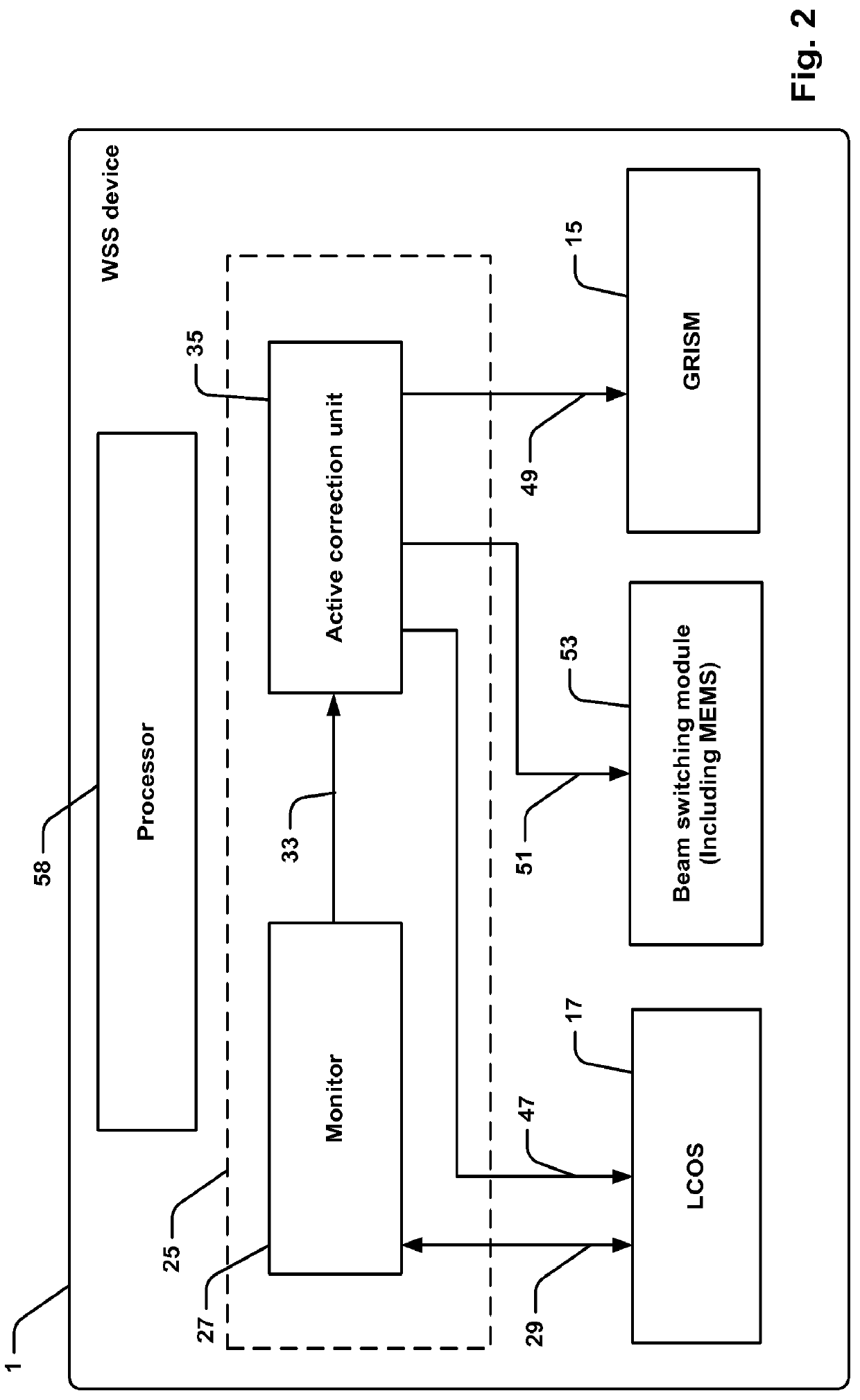
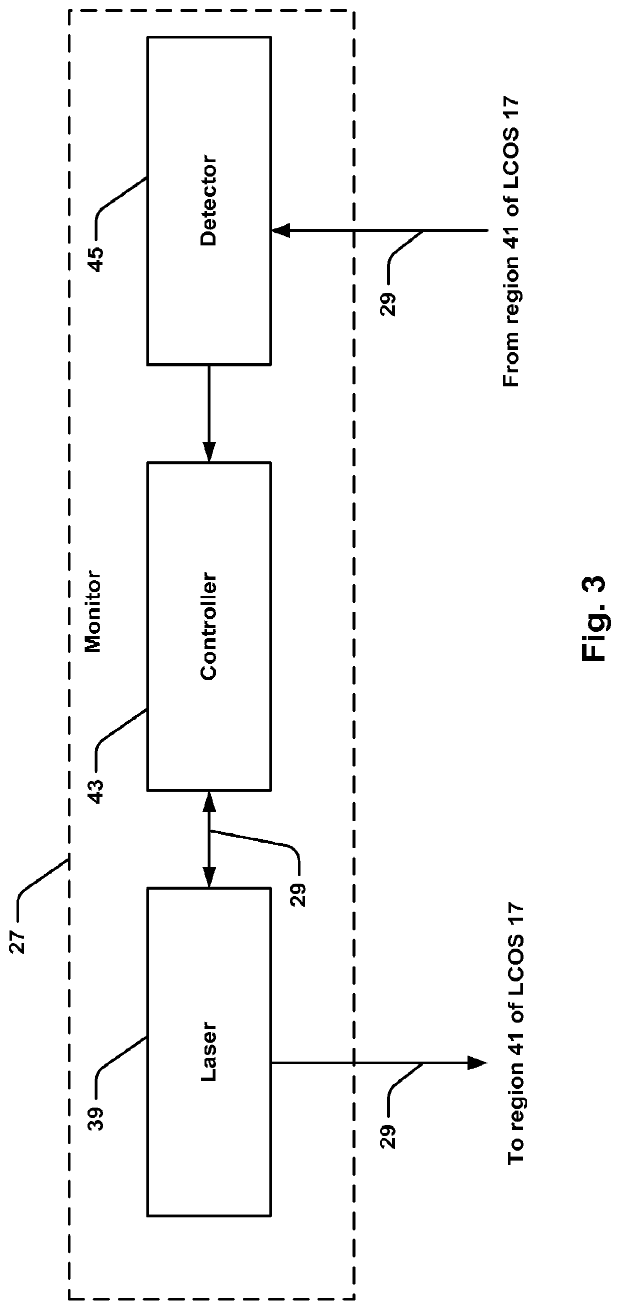
The present invention provides an improved calibration system for a wavelength selective switch that dynamically switches optical beams between input and output ports. The system includes a monitor for projecting an optical monitor beam through the switch and detecting the beam reflected from the switch. The monitor beam is directed onto a predetermined region of the switch and the reflected beam is detected by a detector. The system also includes an active correction unit responsive to the monitor for applying a correction to one or more of the trajectories of the optical beams. The correction can include a predefined spatial offset of the optical beams in the switching dimension. The system can also include a monitor device for monitoring the optical beams and an active feedback controller responsive to the monitor for simultaneously correcting for more than one of beam alignment, wavelength position, and liquid crystal optical flicker. The invention provides a calibration system that improves the accuracy and stability of the wavelength selective switch.

Problems solved by technology

However, these approaches have not been able to be scaled to higher functionality devices such as dual devices or high port count devices.
However, this is problematic because it changes the image of the LCOS, giving rise to problems such as:Transient changes to the port isolation which can be poorly controlled.Difficulties in ensuring calibrations are valid across all operating conditions.Significant variations in the orders of the switching and attenuation images occur as alignment changes, so an uncontrolled order may emerge as a port isolation issue.

Method used


Image

  • Calibration system for a wavelength selective switch
  • Calibration system for a wavelength selective switch
  • Calibration system for a wavelength selective switch

Examples


Embodiment Construction

System Overview

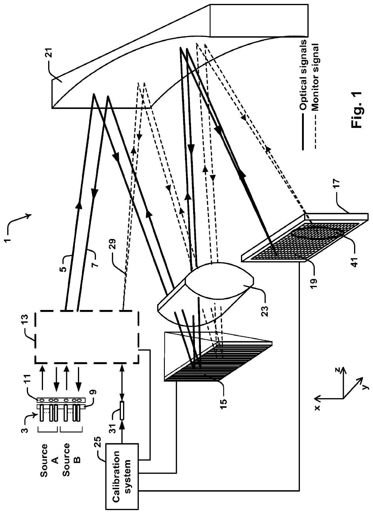
[0074]Preferred embodiments of the present invention have been developed for use in dual source wavelength selective switch (WSS) devices. An exemplary WSS device incorporating two independent optical sources will initially be described with reference to FIG. 1. However, it will be appreciated that the embodiments described herein are applicable to other types of WSS devices such as single source devices and even, in some cases, to other types of optical switches.

[0075]Referring initially to FIG. 1, WSS device 1 includes an array 3 of optical fibers comprising both input optical fibers (common ports) for projecting input optical beams 5 indicative of wavelength division multiplexed optical signals and output optical fibers (add / drop ports) for receiving output optical beams 7 indicative of individual wavelength channels. Array 3 is divided into fibers sourcing beams from two different independent optical sources: Source A and Source B. Ends of fibers in array 3 are mo...


PUM

PropertyMeasurementUnit
distanceaaaaaaaaaa
distanceaaaaaaaaaa
diameteraaaaaaaaaa

Abstract

Described herein is a calibration system (25) for a wavelength selective switch (1). The switch (1) is adapted for dynamically switching optical beams (5, 7) along respective trajectories between input and output ports disposed in an array (3) using a reconfigurable Liquid crystal on silicon (LCOS) spatial light modulator device (17). The calibration system (25) includes a monitor (27) for projecting an optical monitor beam (29) through at least a portion of the switch (1) onto the LCOS (17) and detecting the monitor beam (29) reflected from the LCOS (17). In response, system (25) provides a calibration signal (33) to an active correction unit (35) for applying a correction to one or more of the trajectories while maintaining a constant switching state in the LCOS (17).

Description

CROSS-REFERENCE TO RELATED APPLICATION[0001]This application is a 35 U.S.C. § 371 application based on PCT / US15 / 18322 filed Mar. 2, 2015, entitled “A Calibration System for a Wavelength Selective Switch” which claims priority to U.S. Provisional Patent Application Ser. No. 61 / 947,991, filed Mar. 4, 2014, entitled “A Calibration System for a Wavelength Selective Switch”. The entire disclosures of PCT Patent Application PCT / US15 / 18322 and U.S. Provisional Patent Application Ser. No. 61 / 947,991 and are incorporated herein by reference.FIELD OF THE INVENTION[0002]The present invention relates to optical switching devices and in particular to a calibration system for a wavelength selective switch. While some embodiments will be described herein with particular reference to that application, it will be appreciated that the invention is not limited to such a field of use, and is applicable in broader contexts.BACKGROUND[0003]Any discussion of the background art throughout the specification...

Claims


Application Information

Patent Timeline
Patent Type & Authority Patents(United States)
IPC IPC(8): G02B6/35H04Q11/00G02B26/08
CPCG02B6/3588G02B6/3512G02B26/0833H04Q2011/0039H04Q2011/0083H04Q2011/0026
Inventor FRISKEN, STEVEN JAMES
Owner II VI DELAWARE INC
Features
  • R&D
  • Intellectual Property
  • Life Sciences
  • Materials
  • Tech Scout
  • Unparalleled Data Quality
  • Higher Quality Content
  • 60% Fewer Hallucinations
Learn More