
Floating internal luminescent lighting

a luminescent lighting and floating technology, applied in the direction of light source combinations, identification means, instruments, etc., can solve the problems of privacy and distraction, noise masking techniques that can become uncomfortable for workers in the space, awkward and unproductive intrusions of persons, etc., to reduce clutter, increase usable space, and be beautiful and small

Active Publication Date: 2020-06-09
HEWLETT PACKARD DEV CO LP
View PDF12 Cites 0 Cited by
  • Summary
  • Abstract
  • Description
  • Claims
  • Application Information

AI Technical Summary

Benefits of technology

This patent describes an indicator that uses optical fibers to create a visual pattern of light that is both compact and visually appealing. The indicator can be controlled independently to create more complex patterns. The indicator can also be controlled from a remote location, making it easier to install and adjust for different workplace needs. The technical effects of this invention include improved workplace productivity and etiquette, as well as more efficient and visually appealing decorative lighting.

Problems solved by technology

A problem associated with open office environments relates to privacy and distraction that can be caused by activity of coworkers in the space.
However, noise masking techniques can become uncomfortable to workers in the space over time as they become aware of, or effected by, the masking sounds.
This creates awkward and unproductive intrusions to persons who may need to focus on their workflow, meetings and communication in general.
Also, this type of intrusion can be a problem for individuals who might be working in confidential or private information, and want to keep their current work protected.

Method used


Image

  • Floating internal luminescent lighting
  • Floating internal luminescent lighting
  • Floating internal luminescent lighting

Examples


Embodiment Construction

[0024]A detailed description of embodiments of the present technology is provided with reference to the FIGS. 1-6.

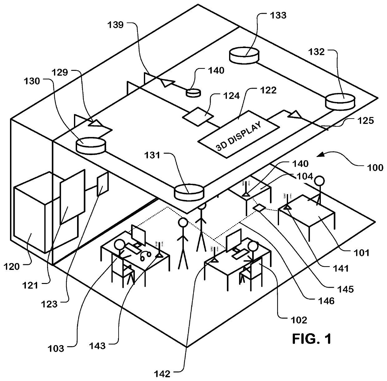
[0025]FIG. 1 illustrates an example of a soundscape system deployed in an open office environment. The open office environment includes workspace 100 in which a number of workstations 101, 102, 103, 104 are arranged.

[0026]The soundscape system includes a computer system 120 which can execute soundscape server programs, in this example, which manage operation of the components of the soundscape system. In other examples, computer system 120 can be an on-premises network node, and include a communication link to a remote network node which executes soundscape management services, by which the soundscape is coordinated using cloud-based soundscape server programs accessed for example via the Internet.

[0027]A plurality of speakers 130, 131, 132, 133 arrayed around the workspace 100, in the ceiling in this example, is used to generate a soundscape sound. An audio driver 129 d...


PUM

PropertyMeasurementUnit
diameteraaaaaaaaaa
diameteraaaaaaaaaa
lengthaaaaaaaaaa

Abstract

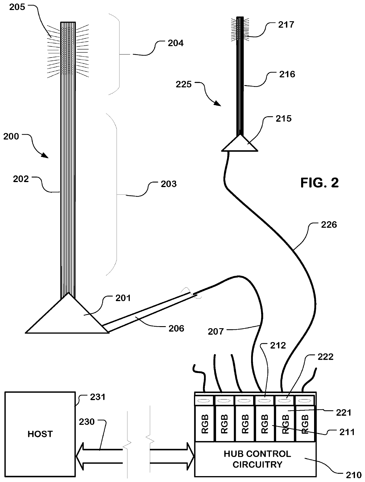
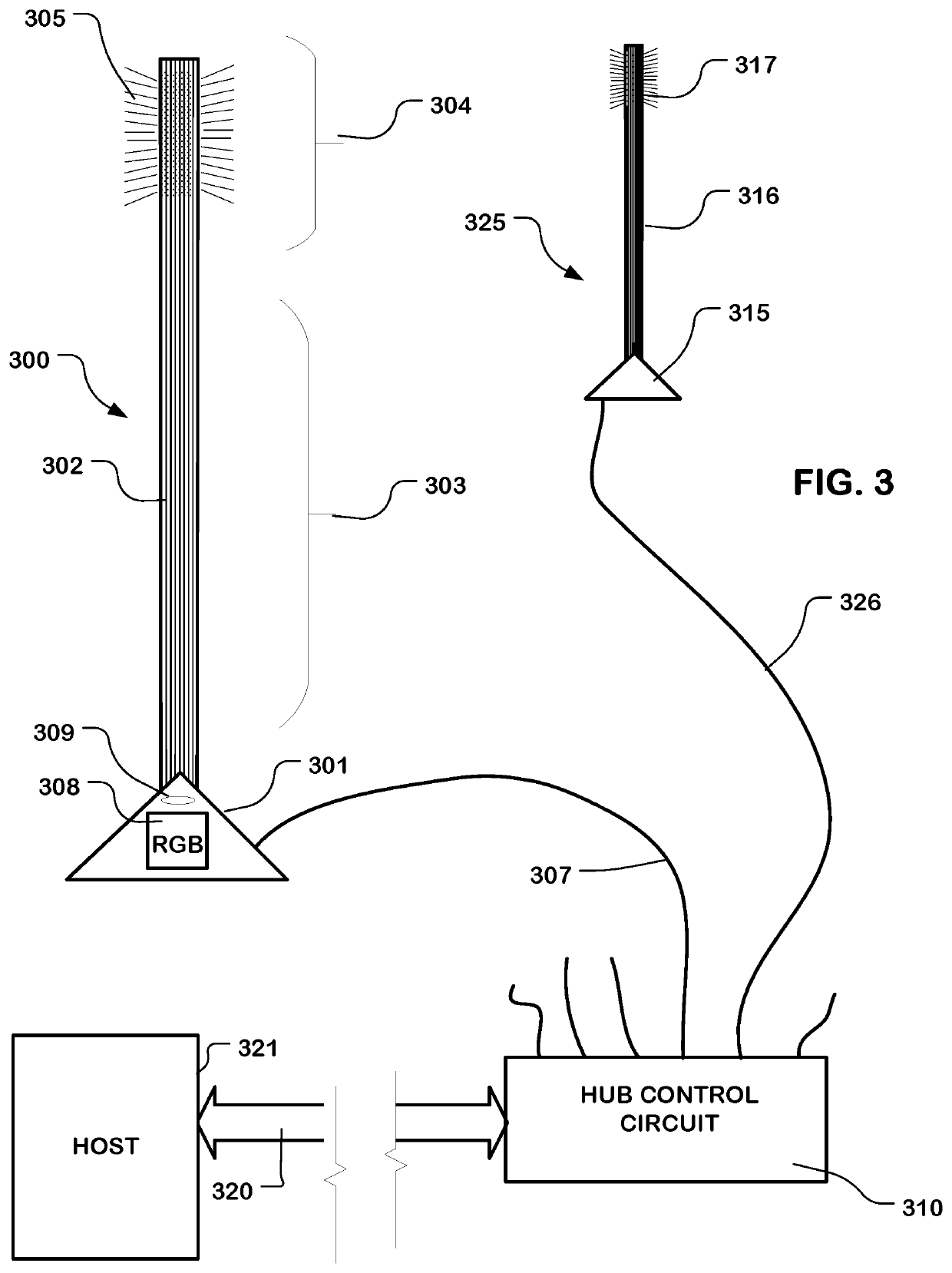
A visual task or status indicator comprises a tube having a riser region extending away from a base and an illumination output region distal to the riser region. The tube has the tube wall comprising an optical diffuser material. A waveguide, such as a polycarbonate strand or other optical fiber or a bundle of optical fibers, is enclosed within and extends through the riser region into the illumination output region of the tube. The waveguide is configured to emit light laterally in the illumination output region. A light source is coupled to the waveguide. The light source can have a plurality of output light modes, including various colors or intensities or patterns of colors and intensities. Control circuitry is connected to the light source to select the output light modes in response to a control signal. A plurality of indicators can be controlled from a central control hub.

Description

BACKGROUNDField[0001]The present invention relates to systems and devices for providing visual indications of status or tasks usable in open office environments, on equipment and in other settings.Description of Related Art[0002]Open office environments are used in many businesses, where they can promote collaboration among workers while making efficient utilization of office space. A problem associated with open office environments relates to privacy and distraction that can be caused by activity of coworkers in the space.[0003]Technologies have been developed to reduce distraction by, for example, projecting sounds, such as so-called white or pink noise, into the environment that mask distracting sounds. However, noise masking techniques can become uncomfortable to workers in the space over time as they become aware of, or effected by, the masking sounds. Natural or biophilic sounds have been used in order to reduce the discomfort generated by white or pink noise.[0004]In the work...

Claims


Application Information

Patent Timeline
Patent Type & Authority Patents(United States)
IPC IPC(8): G08B5/36F21V8/00F21V14/00G08B21/18F21Y113/10
CPCG08B21/18F21V14/006G02B6/001G08B5/36F21Y2113/10G09F9/305G09F19/12
Inventor D'AMBROSIO, JEREMY JACOBBAILEY, CHASE PATRICK
Owner HEWLETT PACKARD DEV CO LP
Learn More