
Methods and apparatus for an amplifier integrated circuit

an amplifier and integrated circuit technology, applied in the direction of gated amplifiers, amplifiers with multiple amplifying elements, gain control, etc., can solve the problems of increasing the noise of the amplifier circuit, and the undesirable effect of increasing the circuit size and increasing the calculation period. , to achieve the effect of low gain bandwidth product, and high gain bandwidth produ

Active Publication Date: 2020-06-16
SEMICON COMPONENTS IND LLC
View PDF7 Cites 3 Cited by
  • Summary
  • Abstract
  • Description
  • Claims
  • Application Information

AI Technical Summary

Benefits of technology

The patent text discusses the problem of conventional amplifiers used in electrical systems. These amplifiers are designed to charge a switched capacitor to a specific level, but sometimes the charging time is too short to allow for the amplifier to operate at high speed. This can lead to increased noise in the amplifier circuit, which is undesirable. The patent describes existing methods to reduce noise, but these methods come with the drawback of increasing circuit size and calculation period. The technical effect of this patent is to provide a solution that reduces noisy amplifier circuits without increasing their size or calculation period.

Problems solved by technology

If an amplifier is set to operate at high speed, a wide range of thermal noise is amplified raising the noise of the amplifier circuit.
While methods to reduce noise level exist, such as including an adding function at the amplifier output, these methods have the undesirable effect of increasing the circuit size and increasing the calculation period.

Method used


Image

  • Methods and apparatus for an amplifier integrated circuit
  • Methods and apparatus for an amplifier integrated circuit
  • Methods and apparatus for an amplifier integrated circuit

Examples


first embodiment

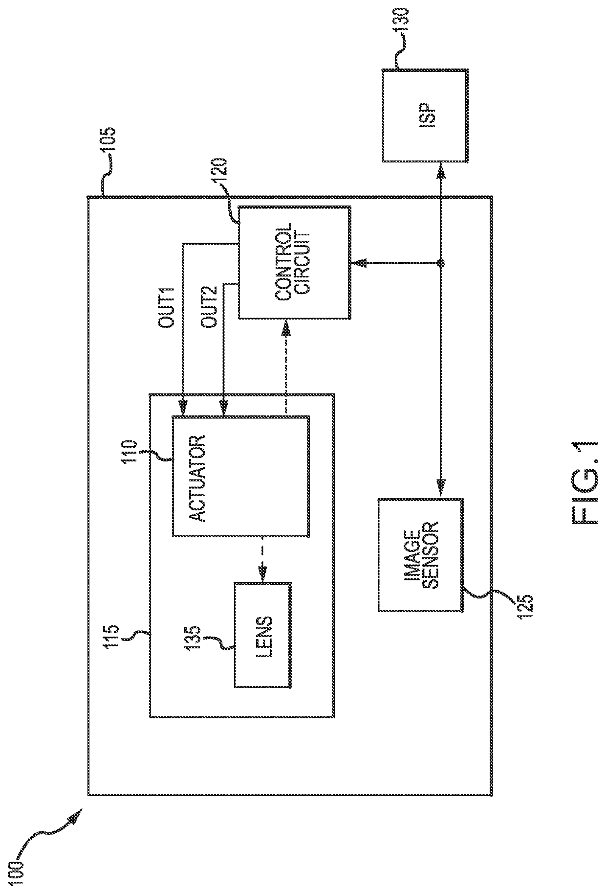
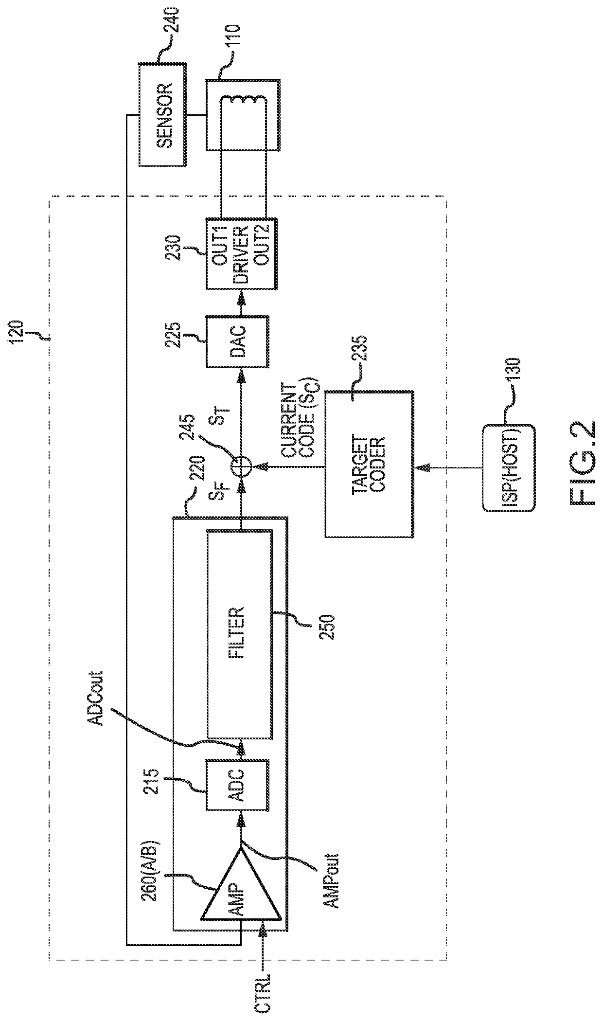
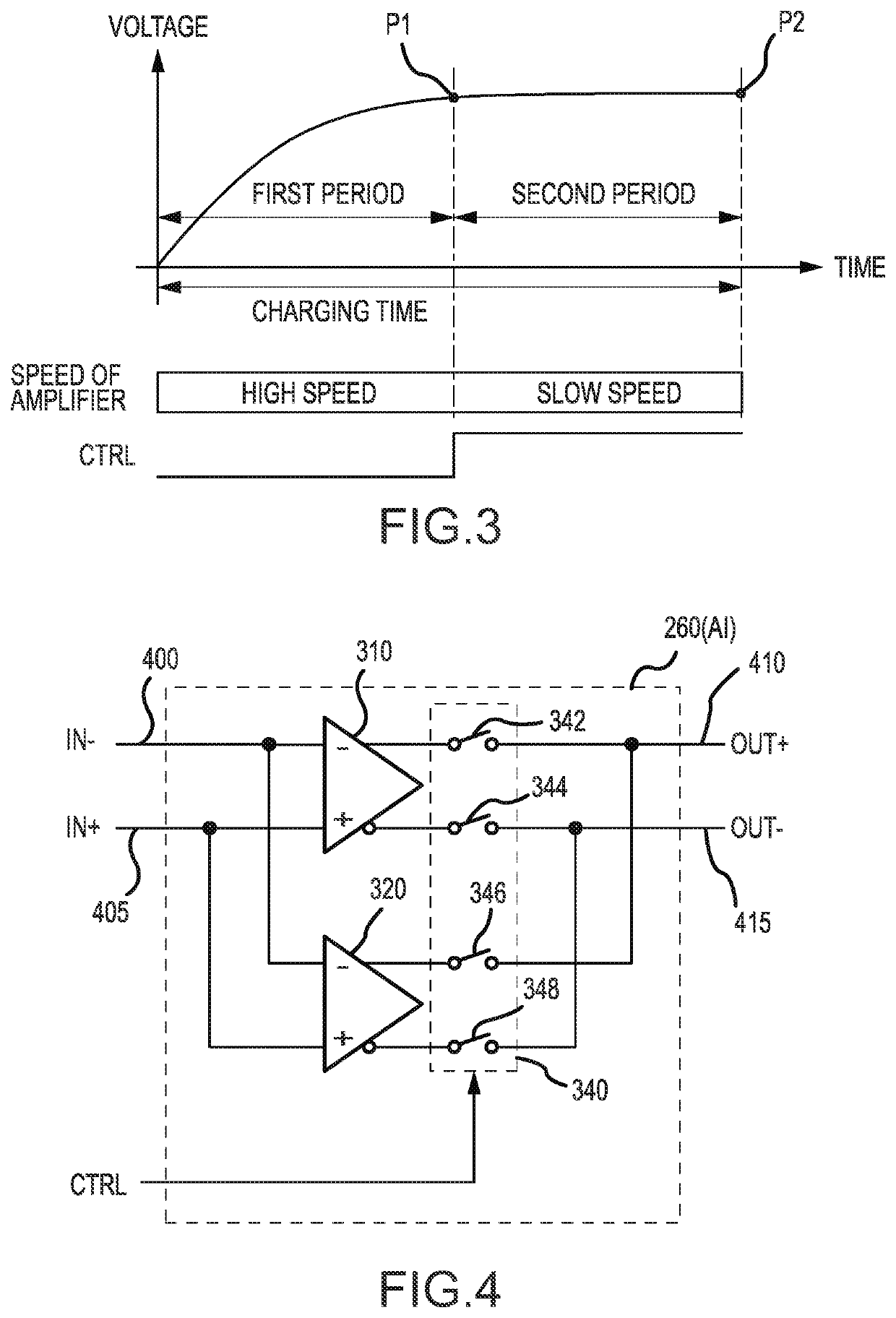
[0045]In a first embodiment and referring to FIGS. 3-11, the amplifier circuit 260(A) may comprise a plurality of amplifiers, such as a first amplifier 310 and a second amplifier 320, and a switching circuit 340. The first and second amplifiers 310, 320 and the switching circuit 340 may be arranged in any configuration suitable for selectively activating one amplifier to provide a particular operating speed. For example, the first amplifier 310 may provide a first gain bandwidth product (GBW), such as a GBW of 1.25 MHz (for example, as illustrated in FIG. 11) and the second amplifier 320 may provide a second gain bandwidth product, such as a GBW of 134 kHz (for example, as illustrated in FIG. 10). The first bandwidth product may correspond to a faster operating speed (i.e., a high speed mode) and the second bandwidth product may correspond to a slower operating speed (i.e., a low speed mode).

[0046]In a first arrangement of the amplifier IC 260(A1), and referring to FIGS. 4-6, the fi...

second embodiment

[0058]In a second embodiment and referring to FIGS. 10-16, the amplifier IC 260(B) may be configured to provide a first gain bandwidth product (GBW), such as a GBW of 1.25 MHz (for example, as illustrated in FIG. 11) and a second gain bandwidth product, such as a GBW of 134 kHz (for example, as illustrated in FIG. 10). The first gain bandwidth product may correspond to a faster operation speed and the second gain bandwidth product may correspond to a slower operation speed.

[0059]In the present embodiment, the amplifier IC 260(B) may comprise multiple switching circuits and a plurality of transistors with a variety of input signals, output signals, bias signals, and groundings. For example, the amplifier IC 260(B) may comprise a first switching circuit 440(A), a second switching circuit 440(B), a first IN+ transistor 501, a second IN+ transistor 502, a first IN− transistor 503, a second IN− transistor 504, a first t1 transistor 511, a second t1 transistor 512, a third t1 transistor 5...


PUM


Abstract

Various embodiments of the present technology may provide methods and apparatus for an amplifier integrated circuit. The amplifier integrated circuit may provide a low gain bandwidth product to amplify at a higher speed and a high gain bandwidth product to amplify at a lower speed. The amplifier integrated circuit may achieve the low and high gain bandwidth product by generating a first current and a second current through a plurality of sets of series-connected transistors and operating a plurality of switches.

Description

CROSS-REFERENCE TO RELATED APPLICATION[0001]This application is a continuation of U.S. patent application Ser. No. 16 / 447,149, filed on Jun. 20, 2019, and incorporates the disclosure of the application in its entirety by reference.BACKGROUND OF THE TECHNOLOGY[0002]Many electrical systems utilize an amplifier to charge a switched capacitor. Conventional amplifiers are designed to charge the capacitor to a particular capacitance. However, if the charging time is fixed to a short period, an amplifier needs to be set to operate at high speed to suit the electrical charging time. If an amplifier is set to operate at high speed, a wide range of thermal noise is amplified raising the noise of the amplifier circuit. While methods to reduce noise level exist, such as including an adding function at the amplifier output, these methods have the undesirable effect of increasing the circuit size and increasing the calculation period.SUMMARY OF THE INVENTION[0003]Various embodiments of the presen...

Claims


Application Information

Patent Timeline
IPC IPC(8): H03F1/02H03F3/45G01D5/24H03G3/30H03F3/72
CPCH03G3/30H03F3/72H03F3/45475H03F1/0205G01D5/24H03F3/45928H03F2203/45514H03F1/26H03F3/42H03F3/45192H03F3/45636H03F2203/45241H03F3/211H03F3/45932H03G1/0088H03G1/0029H03F2203/45541H03F2203/45551
Inventor MURATA, TSUTOMU
Owner SEMICON COMPONENTS IND LLC
Learn More