
Method for producing a customised orthopaedic implant

a technology for orthopaedic implants and manufacturing methods, applied in the field of customisation of orthopaedic implants, can solve the problems of poor patient quality of life, increased risk of prosthesis failure, bone resorption, etc., and achieves favourable strength-to-weight ratio, enhance bone ingrowth, and neutralise stress

Active Publication Date: 2020-06-23
ROYAL MELBOURNE INST OF TECH
View PDF29 Cites 0 Cited by
  • Summary
  • Abstract
  • Description
  • Claims
  • Application Information

AI Technical Summary

Benefits of technology

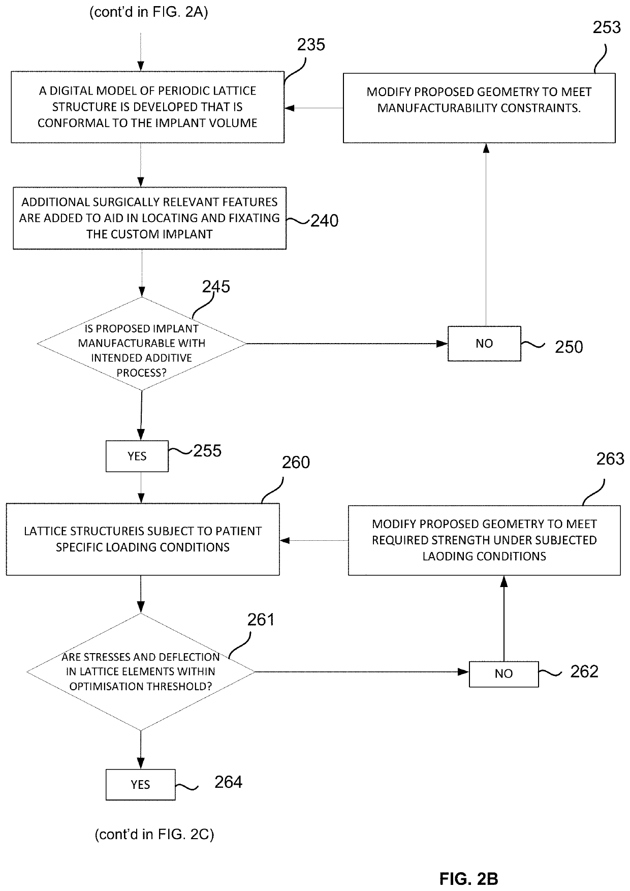
[0009]In a particular embodiment, the customised orthopaedic implant includes a lattice-type geometry. The density of the lattice-type geometry is configured to enhance bone ingrowth and is optimised to neutralise stresses developed at the bone-implant interface. The lattice-type geometry is preferable since it offers a favourable strength to weight ratio, reduces stress shielding and can be manufactured using additive technology. In a more particular embodiment, the lattice-type geometry includes a periodic arrangement. Such an arrangement provides more predictable mechanical properties and behaviour and accordingly, provides greater control over the ultimate performance of the customised orthopaedic implant in-situ. That is, varying the porosity of the lattice structure at a bone / implant interface can be used to enhance bone ingrowth or increase implant stiffness.

Problems solved by technology

Amputation results in poor outcomes for patients in terms of quality of life and accordingly current trends are directed toward trying to salvage the affected limb while resecting the tumour in its entirety to reduce the risk of local recurrence and to maximise the prospects of survival.
For elderly patients, the chances of prosthesis failure are greater, due to reduced physical activity and other age related complications such as osteoporosis.
The disparity in stiffness between the existing bone and the orthopaedic implant can lead to bone resorption and subsequent loosening of the orthopaedic implant.
While in some cases, conventional orthopaedic implants do provide a satisfactory result that allow the patient to return to an active lifestyle, in others, use conventional orthopaedic implants has resulted in extended rehabilitation, pain, discomfort, and lack of mobility.

Method used


Image

  • Method for producing a customised orthopaedic implant
  • Method for producing a customised orthopaedic implant
  • Method for producing a customised orthopaedic implant

Examples


Embodiment Construction

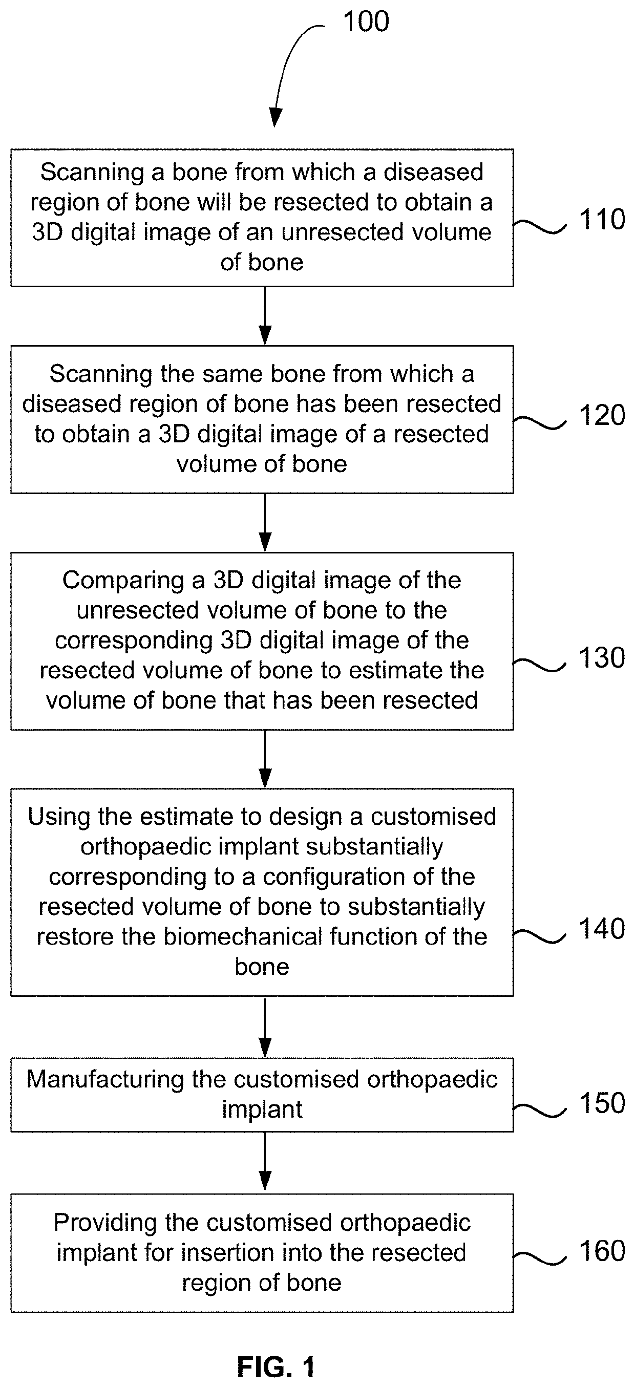
[0033]Referring firstly to FIG. 1, there is shown a flowchart illustrating the method 100 for producing a customised orthopaedic implant. At step 110, a bone from which a diseased region of bone will be resected is scanned to obtain a three dimensional digital image of an unresected volume of bone. At step 120, the same bone from which a diseased region of bone has been resected is scanned to obtain a three dimensional digital image of a resected volume of bone. At step 130, a three dimensional digital image of the unresected volume of bone is compared to the corresponding three dimensional digital image of the resected volume of bone to estimate the volume of bone that has been resected. At step 140, the estimate of the volume of bone that has been resected is used to design a customised orthopaedic implant which substantially corresponds to a configuration of the resected volume of bone. Modelling is performed to ensure proposed customised orthopaedic implant should substantially ...


PUM

PropertyMeasurementUnit
volumeaaaaaaaaaa
stressaaaaaaaaaa
porosityaaaaaaaaaa

Abstract

A method for producing a customised orthopaedic implant is provided. The method involves scanning a bone from which a diseased region of bone will be resected to obtain a three dimensional digital image of an unresected volume of bone; scanning the bone after a diseased region of bone has been resected to obtain a corresponding three dimensional digital image of a resected volume of bone; and comparing the three dimensional digital image of the unresected volume of bone to the corresponding three dimensional digital image of the resected volume of bone to estimate a volume of bone that has been resected. The estimate of the volume of bone that has been resected is used to design a customised orthopaedic implant that substantially corresponds to the configuration of the resected volume of bone, the implant being configured to substantially restore a biomechanical function of the bone. Finally the customised orthopaedic implant is manufactured and provided for insertion into the resected region of bone.

Description

TECHNICAL FIELD[0001]The present invention relates to methods for designing and manufacturing customised orthopaedic implants. More particularly, the method relates to design and production of patient-specific orthopaedic implants for insertion into a resected region of bone.BACKGROUND OF INVENTION[0002]Osteosarcomas are a class of cancer originating from the bone, mainly affecting children or young adults. Prior to the 1970s, amputation was the sole means of treatment available. Amputation results in poor outcomes for patients in terms of quality of life and accordingly current trends are directed toward trying to salvage the affected limb while resecting the tumour in its entirety to reduce the risk of local recurrence and to maximise the prospects of survival. Once the tumour is resected, further surgery is typically required to reconstruct the limb.[0003]Efforts to salvage the limb often involve the insertion of orthopaedic implants to reconstruct the bone or replacement of natu...

Claims


Application Information

Patent Timeline
Patent Type & Authority Patents(United States)
IPC IPC(8): A61F2/28B33Y10/00B29C64/153B29C64/393B29C67/04A61F2/30B33Y50/00B33Y80/00B29L31/00
CPCB29C64/153A61F2/30942B33Y10/00B29C64/393A61F2/28A61F2002/3093A61F2002/30011B33Y80/00A61F2002/3097A61F2002/30952A61F2002/30014A61F2002/30006A61F2240/002A61F2002/3092A61F2002/30962A61F2002/30985B33Y50/00A61F2002/30263A61F2002/30948B29L2031/7532A61F2250/0023
Inventor SHIDID, DARPANLEARY, MARTINBRANDT, MILANCHOONG, PETER
Owner ROYAL MELBOURNE INST OF TECH
Learn More