Wide-angle lens assembly
a wide-angle lens and assembly technology, applied in the field of optical lens assembly, to achieve the effect of large fov, low distortion, and high imaging quality
- Summary
- Abstract
- Description
- Claims
- Application Information
AI Technical Summary
Benefits of technology
Problems solved by technology
Method used
Image
Examples
first embodiment
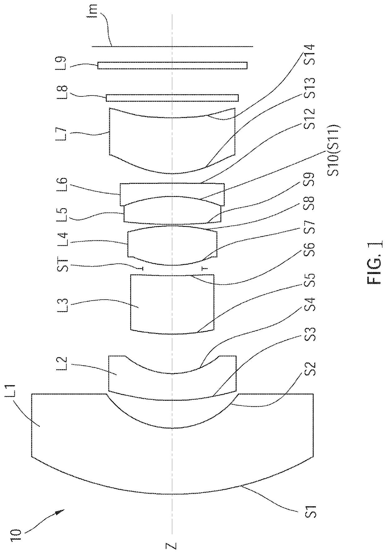
[0024]The following illustrative embodiments and drawings are provided to illustrate the disclosure of the present invention, these and other advantages and effects can be clearly understood by persons skilled in the art after reading the disclosure of this specification. As shown in FIG. 1, a wide-angle lens assembly 10 of a first embodiment according to the present invention includes, in order from an object side to an image side along an optical axis Z, a first lens L1, a second lens L2, a third lens L3, a fourth lens L4, a fifth lens L5, a sixth lens L6, and a seventh lens L7.
[0025]The first lens L1 has negative refractive power, and preferably, the first lens L1 is made of glass and has an object-side surface S1 being convex, and an image-side surface S2 being concave.
[0026]The second lens L2 has negative refractive power, and preferably, the second lens L2 is made of glass and has an object-side surface S3 being convex and an image-side surface S4 being concave. In addition, a...
second embodiment
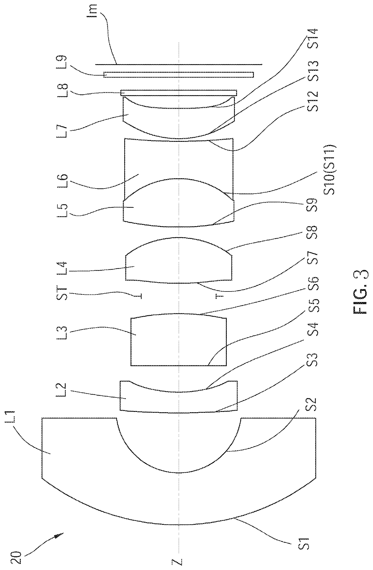
[0045]As shown in FIG. 3, a wide-angle lens assembly 20 of a second embodiment according to the present invention includes, in order from an object side to an image side along an optical axis Z, a first lens L1, a second lens L2, a third lens L3, a fourth lens L4, a fifth lens L5, a sixth lens L6, and a seventh lens L7.
[0046]The first lens L1 has negative refractive power, and preferably, the first lens L1 is made of glass and has an object-side surface S1 being convex, and an image-side surface S2 being concave.
[0047]The second lens L2 has negative refractive power, and preferably, the second lens L2 is made of glass. In addition, at least one surface of the second lens L2 is aspheric, for example, in the current embodiment, both of an object-side surface S3 and an image-side surface S4 of the second lens L2 are aspheric surfaces.
[0048]The third lens L3 has positive refractive power, and preferably, the third lens L3 is made of glass and has an object-side surface S5 being convex a...
third embodiment
[0066]As shown in FIG. 5, a wide-angle lens assembly 30 of a third embodiment according to the present invention includes, in order from an object side to an image side along an optical axis Z, a first lens L1, a second lens L2, a third lens L3, a fourth lens L4, a fifth lens L5, a sixth lens L6, and a seventh lens L7.
[0067]The first lens L1 has negative refractive power, and preferably, the first lens L1 is made of glass and has an object-side surface S1 being convex, and an image-side surface S2 being concave.
[0068]The second lens L2 has negative refractive power, and preferably, the second lens L2 is made of glass. In addition, at least one surface of the second lens L2 is aspheric. For example, in the current embodiment, both of an object-side surface S3 and an image-side surface S4 of the second lens L2 are aspheric surfaces.
[0069]The third lens L3 has positive refractive power, and preferably, the third lens L3 is made of glass and has an object-side surface S5 being substanti...
PUM
 Abstract
Description
Claims
Application Information
 - R&D
- Intellectual Property
- Life Sciences
- Materials
- Tech Scout
- Unparalleled Data Quality
- Higher Quality Content
- 60% Fewer Hallucinations
Browse by: Latest US Patents, China's latest patents, Technical Efficacy Thesaurus, Application Domain, Technology Topic, Popular Technical Reports.
© 2025 PatSnap. All rights reserved.Legal|Privacy policy|Modern Slavery Act Transparency Statement|Sitemap|About US| Contact US: help@patsnap.com


