Coated article with low-E coating having protective contact layer including Ag, Ni, and Cr for protecting silver based IR reflecting layer(s), and method of making same

a technology of low-e coating and protective contact layer, which is applied in the direction of metal layered products, layered products, chemistry apparatus and processes, etc., can solve the problems of high visible transmission and poor performance of low-e coatings, and achieve low u-values, low emissivity, and low resistance of sheets

Active Publication Date: 2020-06-30
GUARDIAN EURO S A R L
View PDF24 Cites 0 Cited by
  • Summary
  • Abstract
  • Description
  • Claims
  • Application Information

AI Technical Summary

Benefits of technology

[0002]Coated articles are known in the art for use in window applications such as insulating glass (IG) window units, vehicle windows, monolithic windows, and / or the like. In certain example instances, designers of coated articles often strive for a combination of high visible transmission, substantially neutral color, low emissivity (or emittance), low sheet resistance (Rs), low U-values in the context of IG window units, and / or low specific resistivity. High visible transmission and substantially neutral color may permit coated articles to be used in applications where these characteristics are desired such as in architectural or vehicle window applications, whereas low-emissivity (low-E), low sheet resistance, and low specific resistivity characteristics permit such coated articles to block significant amounts of IR radiation so as to reduce for example undesirable heating of vehicle or building interiors.

Problems solved by technology

While there are some durable low-E coatings in the market, their performances are sometimes poor especially with respect to undesirably low light-to-solar gain ratio (LSG) values of around 1.0 or less, because it is often difficult to achieve high visible transmission (Tvis) along with other desirable features in a low-E coating.

Method used


Image

  • Coated article with low-E coating having protective contact layer including Ag, Ni, and Cr for protecting silver based IR reflecting layer(s), and method of making same
  • Coated article with low-E coating having protective contact layer including Ag, Ni, and Cr for protecting silver based IR reflecting layer(s), and method of making same
  • Coated article with low-E coating having protective contact layer including Ag, Ni, and Cr for protecting silver based IR reflecting layer(s), and method of making same

Examples


Embodiment Construction

[0012]Referring now to the drawings in which like reference numerals indicate like parts throughout the several views.

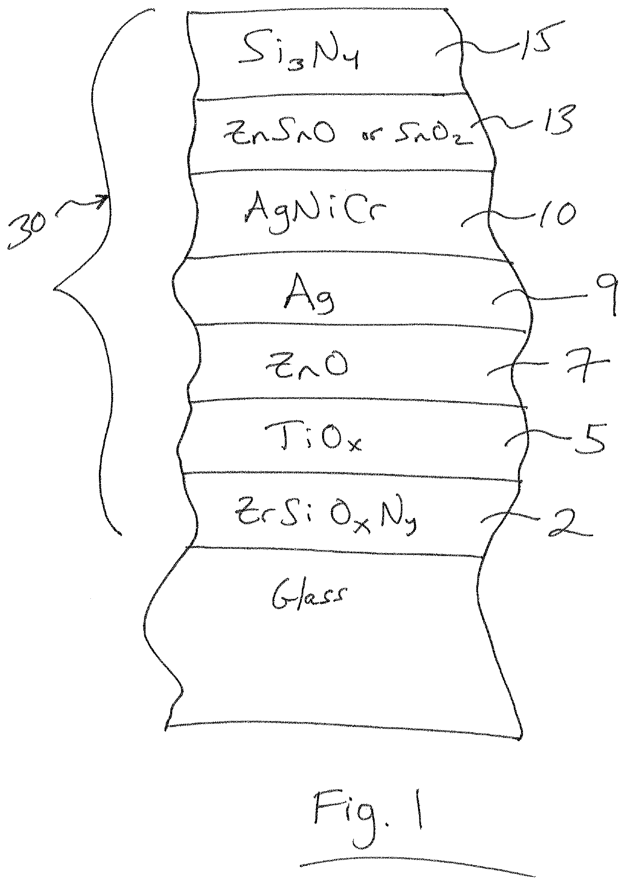
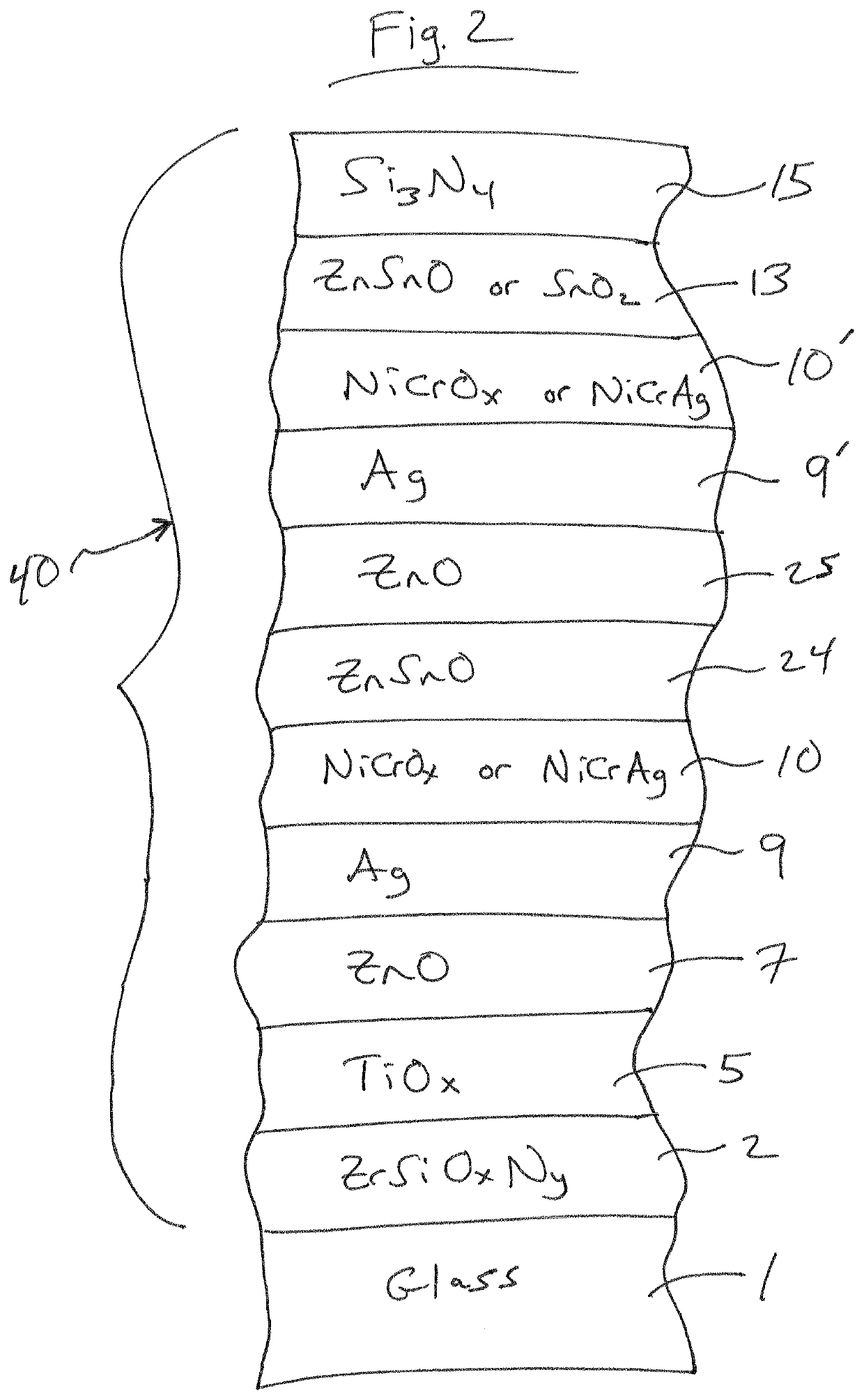
[0013]Example embodiments of this invention relate to a coated article including a glass substrate 1 that supports a low-E coating 30, 40. The low-E coating 30, 40 is designed to have good silver durability (e.g., chemical durability) and desirably visible transmission, while preferably maintaining high SF and / or LSG values.

[0014]According to certain example embodiments, the low-E coating (e.g., 30 and / or 40) includes at least one silver (Ag) based infrared (IR) reflecting layer(s) 9, 9′ that is provided adjacent to and contacting at least one contact layer 10, 10′ of or including Ag, Ni and Cr. It has surprisingly been found that the provision of a contact layer(s) 10, 10′ including at least Ag, Ni and Cr, directly over and contacting a silver-based IR reflecting layer 9, 9′, advantageously increases visible transmission (Tvis) of the low-E coating (compared to usin...


PUM

PropertyMeasurementUnit
sheet resistanceaaaaaaaaaa
emissivityaaaaaaaaaa
sheet resistanceaaaaaaaaaa

Abstract

A coated article includes a low emissivity (low-E) coating supported by a glass substrate. The low-E coating includes at least one silver (Ag) based infrared (IR) reflecting layer(s) that is provided adjacent to and contacting at least one contact layer of or including Ag, Ni and Cr. The provision of a contact layer(s) including at least Ag, Ni and Cr, directly over and contacting a silver-based IR reflecting layer, has been found to advantageously increase visible transmission (Tvis) of the low-E coating. Such low-E coating may be used in applications such as monolithic windows, insulated glass (IG) window units, and the like.

Description

[0001]This application relates in certain example embodiments to a coated article including a coating comprising at least one silver (Ag) based infrared (IR) reflecting layer(s) that is provided adjacent to and contacting at least one contact layer of or including Ag, Ni and Cr. The provision of a contact layer(s) including at least Ag, Ni and Cr, directly over and contacting a silver-based IR reflecting layer, has been found to advantageously increase visible transmission (Tvis) of the low-E coating (compared to using a NiCr contact layer). The provision of the contact layer(s) including at least Ag, Ni and Cr, directly over and contacting a silver-based IR reflecting layer, has also been found to advantageously increase solar factor (SF) and / or light-to-solar gain ratio (LSG) of the low-E coating, while not sacrificing emissivity and / or sheet resistance. The silver based IR reflecting layer, and adjacent contact layer(s) including at least Ag, Ni and Cr, are part of a low emissivi...

Claims


Application Information

Patent Timeline
Patent Type & Authority Patents(United States)
IPC IPC(8): B32B15/04C03C17/36B32B17/06
CPCC03C17/3644C03C17/36C03C17/366C03C17/3626C03C17/3652
Inventor DIETRICH, ANTONDISTELDORF, BERND
Owner GUARDIAN EURO S A R L
Why Eureka
Try Eureka