Wavelength conversion device, light source device, lighting apparatus, and projection image display apparatus
a technology of wavelength conversion and light source, which is applied in the direction of fixed installation, lighting and heating equipment, instruments, etc., can solve the problems of reducing the use efficiency of fluorescent light emitted by the first phosphor particle, and difficulty in implementing desired color rendering properties
- Summary
- Abstract
- Description
- Claims
- Application Information
AI Technical Summary
Benefits of technology
Problems solved by technology
Method used
Image

Examples
embodiment 1
[0023](Configuration of Wavelength Conversion Device)
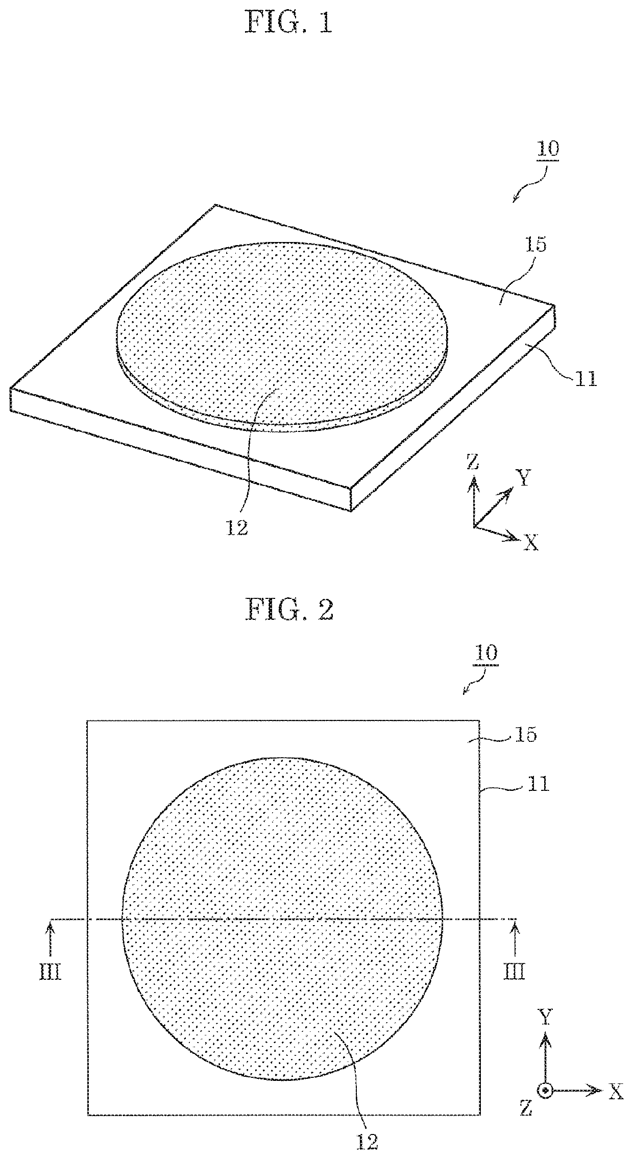
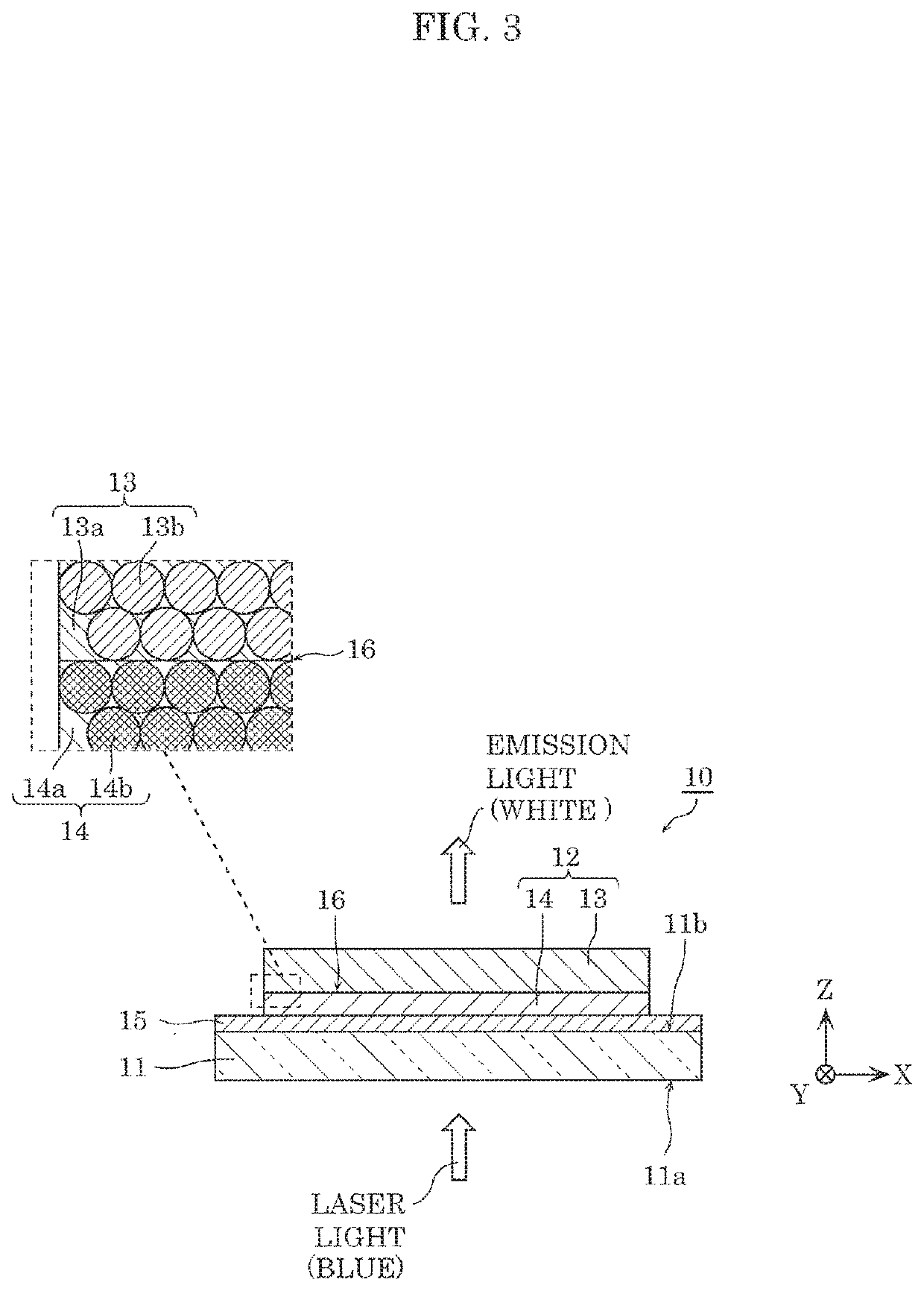
[0024]First, a configuration of a wavelength conversion device according to Embodiment 1 will be described with reference to the drawings. FIG. 1 is an external perspective view of the wavelength conversion device according to Embodiment 1. FIG. 2 is a plan view of the wavelength conversion device according to Embodiment 1. FIG. 3 is a schematic cross-sectional view of the wavelength conversion device, taken along the line III-III of FIG. 2. It should be noted that, in FIG. 3, there are instances where a magnitude correlation between the thicknesses of the structural components, for example, is not precisely described.
[0025]Wavelength conversion device 10 according to Embodiment 1 illustrated in FIG. 1 to FIG. 3 is a device that emits fluorescent light when excited by excitation light. Specifically, wavelength conversion device 10 includes light-transmissive substrate 11, phosphor layer 12, and optical thin film 15. Phosphor layer...
embodiment 2
[0076](Overall Configuration)
[0077]In Embodiment 2, a light source device including wavelength conversion device 10, and a lighting apparatus including the light source device will be described. FIG. 5 is an external perspective view of the lighting apparatus according to Embodiment 2. FIG. 6 is a schematic cross-sectional view which illustrates a use mode of the lighting apparatus according to Embodiment 2. It should be noted that, in FIG. 6, only the illustration of power supply device 40 shows a side surface instead of a cross-section surface.
[0078]As illustrated in FIG. 5 and FIG. 6, lighting apparatus 100 is a downlight attached to ceiling 50 of a building. Lighting apparatus 100 includes light source device 20, lighting device 30, and power supply device 40. Light source device 20 and lighting device 30 are optically connected via optical fiber 23. Light source device 20 and power supply device 40 are electrically connected via power supply cable 24.
[0079]Lighting apparatus 10...
embodiment 3
[0097]In Embodiment 3, a light source device including wavelength conversion device 10, and a projection image display apparatus including the light source device will be described. FIG. 7 is an external perspective view of the projection image display apparatus according to Embodiment 3. FIG. 8 is a diagram which illustrates an optical system of the projection image display apparatus according to Embodiment 3.
[0098]As illustrated in FIG. 7 and FIG. 8, projection image display apparatus 200 is a single-plate projector. Projection image display apparatus 200 includes light source device 60, collimate lens 71, integrator lens 72, polarized beam splitter 73, condenser lens 74, and collimate lens 75. In addition, projection image display apparatus 200 includes entrance-side polarization element 76, imaging element 80, exit-side polarization element 77, and projection lens 90.
[0099]Light source device 60 emits white light including excitation light (blue laser light) and fluorescent ligh...
PUM
| Property | Measurement | Unit |
|---|---|---|
| peak wavelength | aaaaa | aaaaa |
| peak wavelength | aaaaa | aaaaa |
| peak wavelength | aaaaa | aaaaa |
Abstract
Description
Claims
Application Information
 - R&D
- Intellectual Property
- Life Sciences
- Materials
- Tech Scout
- Unparalleled Data Quality
- Higher Quality Content
- 60% Fewer Hallucinations
Browse by: Latest US Patents, China's latest patents, Technical Efficacy Thesaurus, Application Domain, Technology Topic, Popular Technical Reports.
© 2025 PatSnap. All rights reserved.Legal|Privacy policy|Modern Slavery Act Transparency Statement|Sitemap|About US| Contact US: help@patsnap.com