Film dispersed of carbon nanotubes and light emitting body
a technology of carbon nanotubes and carbon nanotubes, applied in nanotechnology, nanotechnology, coatings, etc., can solve the problem of unstable orientation state, achieve high rigidity, ease of application to various fields, and high rigidity
- Summary
- Abstract
- Description
- Claims
- Application Information
AI Technical Summary
Benefits of technology
Problems solved by technology
Method used
Image
Examples
first embodiment
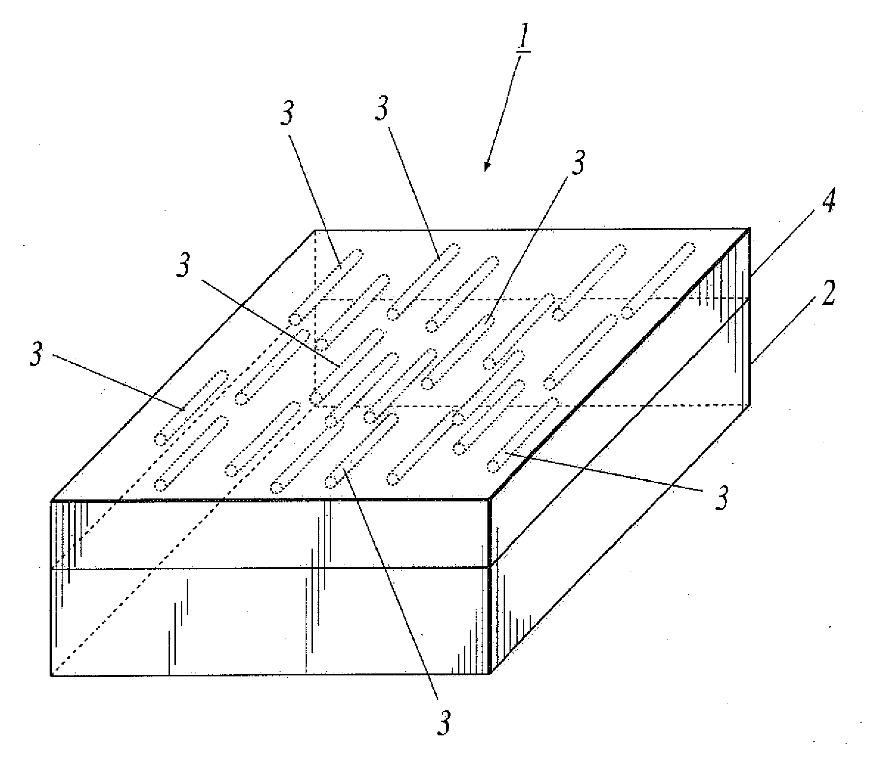
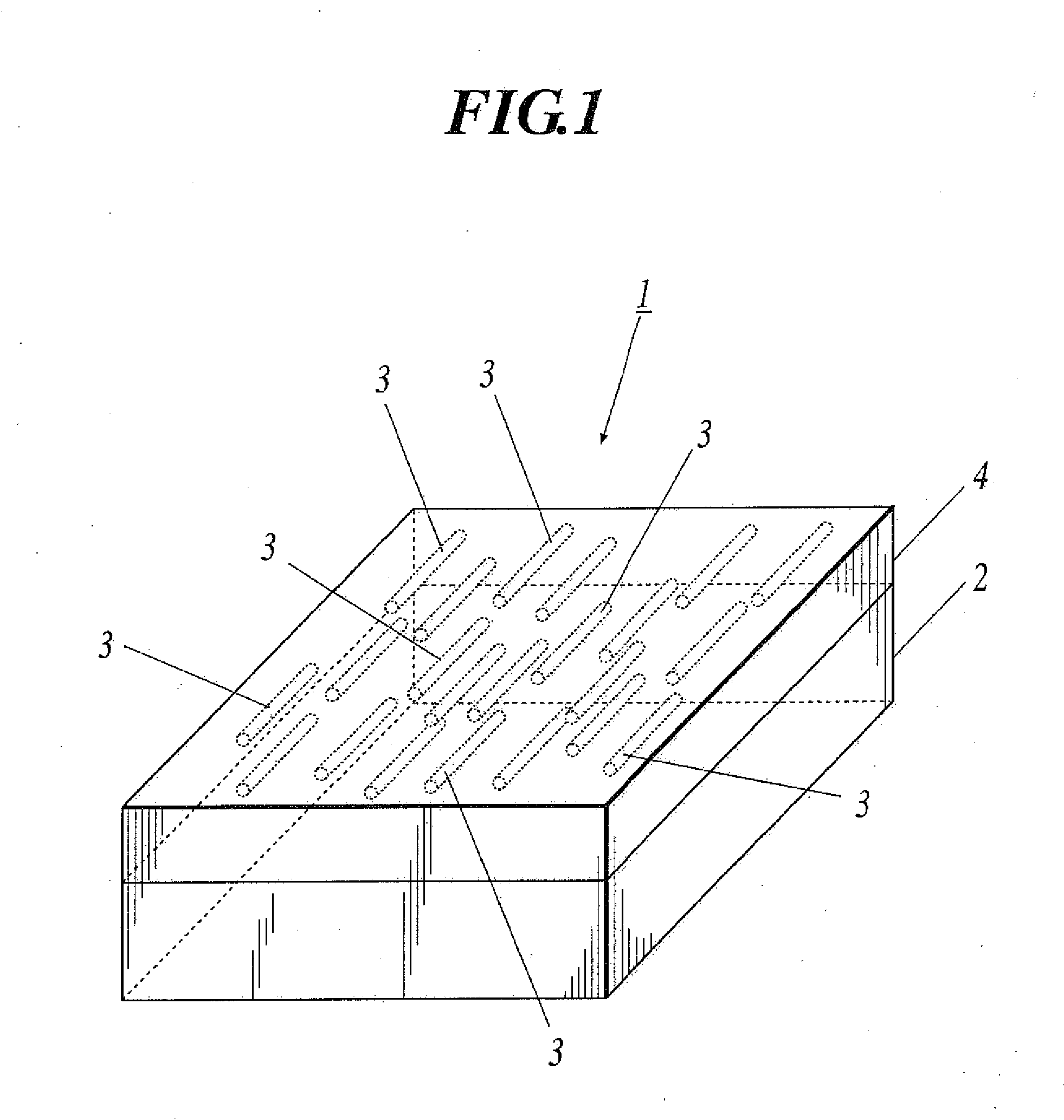
[0033]FIG. 1 is a perspective view showing a schematic structure of light emitting body 1 according to the first embodiment.
[0034]As shown in FIG. 1, the light emitting body 1 is provided with a substrate 2 that has a rectangular shape. A film dispersed of carbon nanotubes 4 which has a plurality of carbon nanotubes 3, 3, . . . dispersed is formed on the substrate 2.
[0035]As for the substrate 2, material with any property among insulating property, conductive property, and semi-conductive property can be applied. For example, materials such as quartz, glass, quartz glass, ceramics, metal, silicone, and the like can be used. In a case where the substrate 2 is structured with glass, it is preferable to use transparent glass such as soda-lime glass, low soda glass, lead-alkali-silicate glass, borosilicate glass, and the like. In particular, it is preferable to structure the substrate 2 with a high strain point low soda glass and low soda glass. In a case where the substrate 2 is struct...
second embodiment
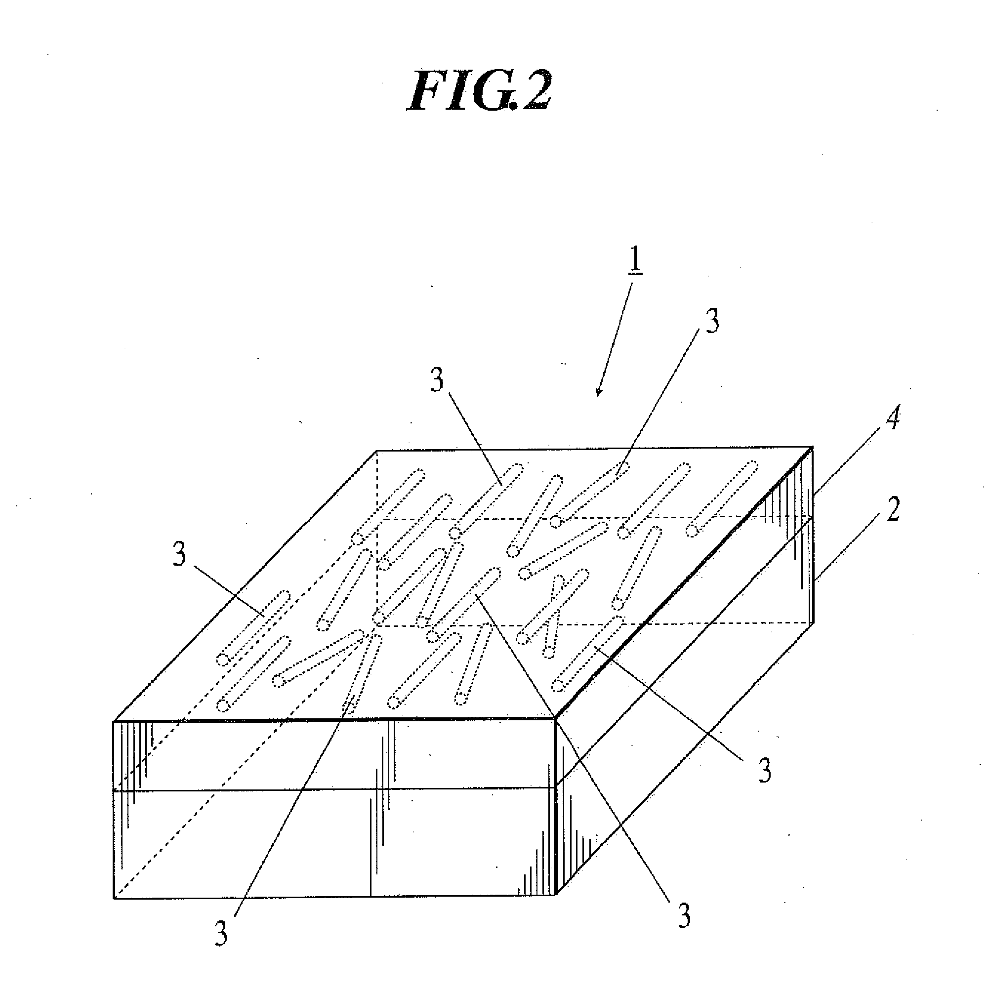
[0079]FIG. 2 is a perspective view showing a schematic structure of a light emitting body according to the second embodiment.
[0080]As shown in FIG. 2, the light emitting body 1 according the second embodiment differs from the light emitting body 1 according to the first embodiment, concerning the state of each carbon nanotube 3 in the film dispersed of carbon nanotubes 4. Other structure is the same as the first embodiment. That is, concerning the light emitting body 1 shown in FIG. 2, each carbon nanotube 3 is only dispersed isolatedly (in an isolated state) in the film dispersed of carbon nanotubes 4, and each carbon nanotube 3 is not oriented in a certain direction.
[0081]The manufacturing method of light emitting body 1 and the film dispersed of carbon nanotubes 4 according to the second embodiment are different from the manufacturing method of light emitting body 1 and the film dispersed of carbon nanotubes 4 according to the first embodiment in only a few steps, and other steps...
example 1
(1) Preparation of Test Sample A
[0085]To a D2O solution which was prepared by adding 100 mg of SDS to 10 g of D2O, 15 mg of known single-walled carbon nanotube formed by HiPco method was added to obtain HiPco containing solution. After the HiPco containing solution was obtained, ultrasonic processing was applied to the HiPco containing solution by a horn sonicator, for one hour within water-cooling at 10-15 degrees Celsius with output of 400 W.
[0086]After the ultrasonic dispersion processing was concluded, ultracentrifuge processing was applied to the HiPco containing solution after ultrasonic dispersion processing, with 330,000 g (plus minus 50,000 g) of load under 22 degrees Celsius for one hour. After the ultracentrifuge processing was concluded, upper 30% and lower 30% (including precipitation) was eliminated from the clear upper portion of the HiPco containing solution after ultracentrifuge processing, and the central 40% of the clear upper portion was collected to obtain HiPco...
PUM
| Property | Measurement | Unit |
|---|---|---|
| diameter | aaaaa | aaaaa |
| temperature | aaaaa | aaaaa |
| temperature | aaaaa | aaaaa |
Abstract
Description
Claims
Application Information
 - R&D
- Intellectual Property
- Life Sciences
- Materials
- Tech Scout
- Unparalleled Data Quality
- Higher Quality Content
- 60% Fewer Hallucinations
Browse by: Latest US Patents, China's latest patents, Technical Efficacy Thesaurus, Application Domain, Technology Topic, Popular Technical Reports.
© 2025 PatSnap. All rights reserved.Legal|Privacy policy|Modern Slavery Act Transparency Statement|Sitemap|About US| Contact US: help@patsnap.com


