
Filter device for fluids

a filter device and fluid technology, applied in the direction of filtration separation, magnetic separation, solid separation, etc., can solve the problems of impaired filtration process and the change of used filter elements to new filter elements, and achieve the effect of improving operating performance and convenient operation of devices

Active Publication Date: 2020-07-07
HYDAC PROCESS TECH
View PDF7 Cites 0 Cited by
  • Summary
  • Abstract
  • Description
  • Claims
  • Application Information

AI Technical Summary

Benefits of technology

The invention is a filter device that improves filtration performance and makes it easier to operate. It uses a magnet to capture particles before they reach the filter, reducing the amount of maintenance required. The device also has a housing with a stand, making it easy to replace the filter element. The bottom of the housing has an outlet for flushing off the captured particles, keeping the device clean. The technical effects of the invention include improved performance, easy operation, and efficient maintenance.

Problems solved by technology

In this manner, neither the filtration process nor the change of a used filter element to a new filter element are impaired.

Method used


Image

  • Filter device for fluids
  • Filter device for fluids
  • Filter device for fluids

Examples


Embodiment Construction

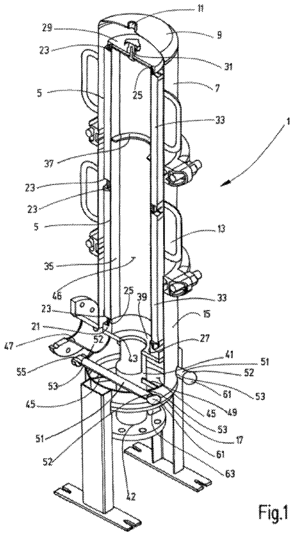
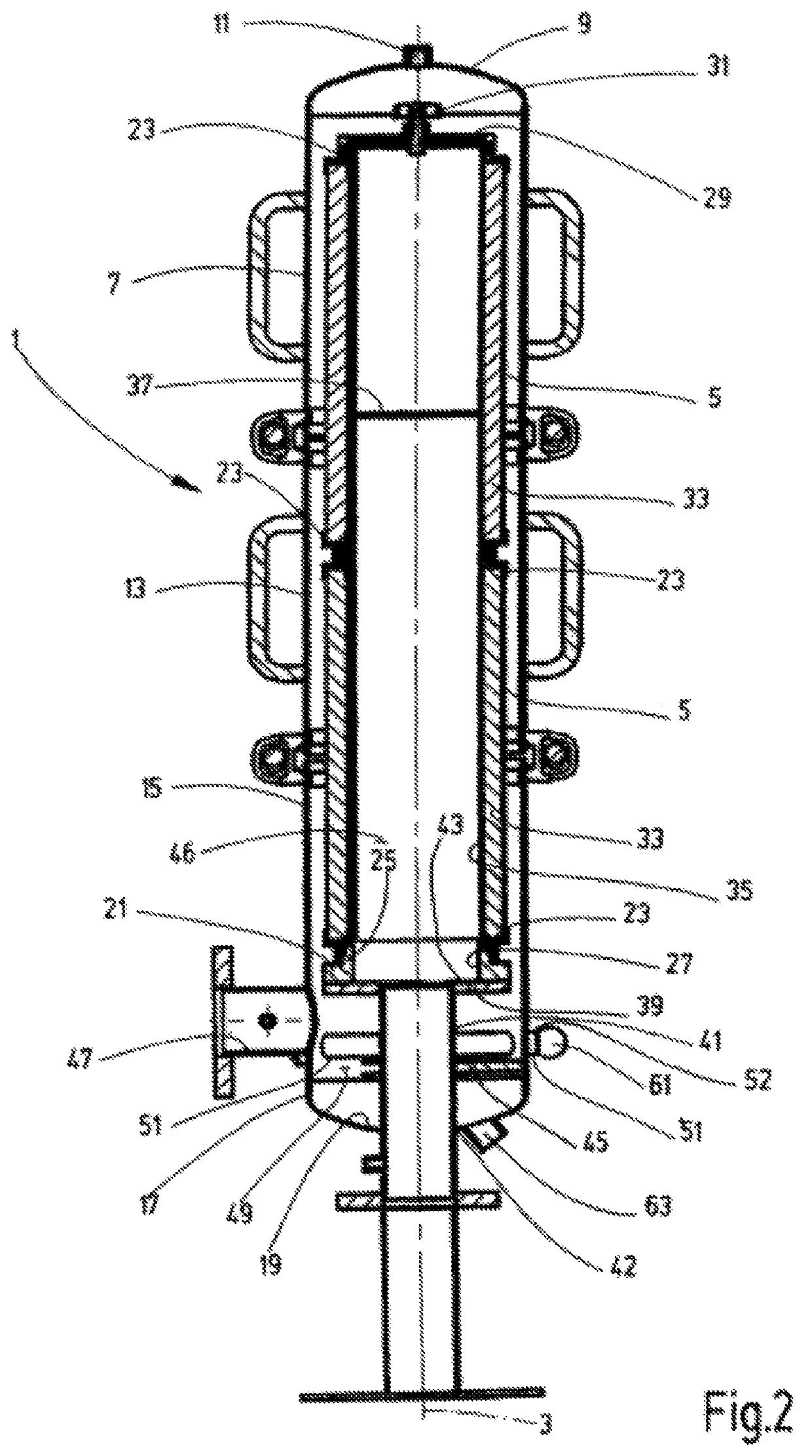
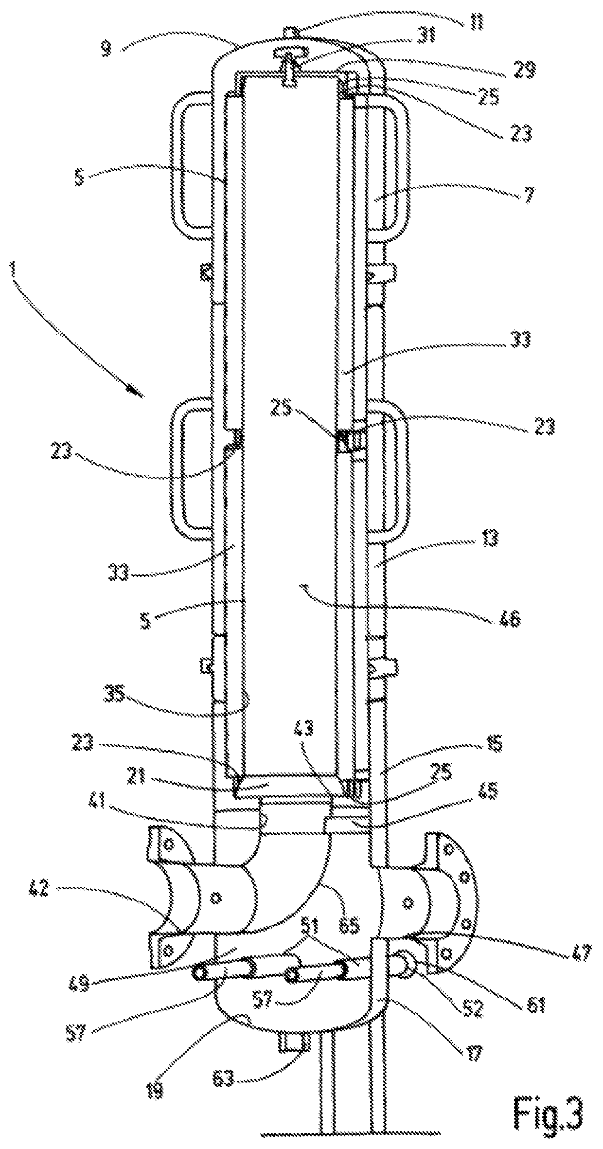
[0026]The invention is described by way of exemplary embodiments with reference to the attached drawings. In a circular-cylindrical filter housing 1, which extends along a vertical axis 3 (FIG. 2), a filter cartridge may be housed. In the examples shown, the filter cartridge is formed by two filter elements 5 of equal design. The housing 1 is formed by three housing sections that are screwed together. The top housing section 7 is closed off through an upper end section 9, which is provided with a centrally located, closable vent opening 11. Following the upper housing section 7 is a central, tubular housing section 13, followed by a lower housing section 15. This lower housing section 15 merges into a bottom part 17 that forms the lower housing end. The base 19 of the bottom part 17 has a slightly outwardly-domed bottom area.

[0027]To support the filter cartridge, which is made up of the filter elements 5, an element seat 21 is provided in form of an annular member. The annular membe...


PUM

PropertyMeasurementUnit
Magnetic fieldaaaaaaaaaa
Distanceaaaaaaaaaa
Magnetismaaaaaaaaaa

Abstract

A filter device for fluids includes a housing (1) accommodating a filter element (5). The housing has an inlet (47) for the supply of fluid to be purified to a non-filtrate chamber (49) of the housing (1) and has an outlet 42 for the filtrate. The non-filtrate chamber is separated from a filtrate chamber (46) of the housing (1) by the filter medium (33). A magnetic field-generator unit (57) is arranged inside the non-filtrate chamber (49). An adhering surface a sleeve or casing (51) attracts ferromagnetic particles by a magnetic force effect. In the non-filtrate chamber (49), the sleeve (51) extends outside of the respective filter element (5) parallel to the inlet (47) and transversely to the outlet (42). The non-filtrate chamber (49) at least partially encompasses the outlet (42) at the point of transition to the filtrate chamber (46).

Description

FIELD OF THE INVENTION[0001]The invention concerns a filter device for fluids having a filter element and a magnetic field for attracting ferromagnetic particles against a surface of a sleeve.BACKGROUND OF THE INVENTION[0002]Pre-scalping of ferromagnetic contaminants from the fluid to be filtered using magnetic force is prior art for filter devices. Plant machinery that employs a fluid circuit for lubrication and / or cooling of mechanical equipment, such as transmissions or pumps, always have metal particles present in the fluid through friction during operation, in particular in the instance of transmissions that are under high load in heavy machinery such as wind turbines or cement mills. Ferromagnetic contamination of the fluid also occurs in other kinds of process fluids to a varying degree. In particular in detergent solutions often used in plants for the automatic manufacture of parts, a high concentration of ferromagnetic particles can be found in the fluid. The separation of ...

Claims


Application Information

Patent Timeline
IPC IPC(8): B01D29/54B01D29/15B01D29/21B01D35/06B03C1/28
CPCB01D29/54B03C1/286B01D29/21B01D35/06B01D29/15B03C2201/18B01D35/30
Inventor OLSCHOK, MARKUSSCHINDLER, CHRISTIANSCHWARZKOPF, ALEXANDER
Owner HYDAC PROCESS TECH
Learn More