Vehicle

a battery pack and vehicle technology, applied in the field of vehicles, can solve the problems the increase in the amount of the support member, and the easy shock of the road surface, so as to achieve the effect of increasing the weight of the battery pack, increasing the amount of the support member, and increasing the strength of the battery pack

Active Publication Date: 2020-07-07
TOYOTA JIDOSHA KK
View PDF23 Cites 1 Cited by
  • Summary
  • Abstract
  • Description
  • Claims
  • Application Information

AI Technical Summary

Benefits of technology

[0005]In such a vehicle, the battery pack interferes with, for example, a fallen object on a road surface or a height difference of a road surface, and is easily subjected to shock from the road surface. Therefore, it is conceivable to provide a plurality of support members in the battery pack for reinforcement. However, if the plurality of support members are provided uniformly, the support members are provided even in a region that does not require high strength, which leads to an increase in amount of the support members. As a result, a weight of the battery pack may increase.
[0006]Accordingly, an object of the present disclosure is to solve the above-described problem and provide a vehicle that makes it possible to appropriately protect a battery pack against shock from a road surface, while suppressing an increase in weight.
[0008]According to the vehicle configured as described above, the plurality of support members are provided at different area ratios in the central region and in the rear region, and thus, an amount of the support members can be reduced. As a result, an increase in weight of the battery pack caused by placement of the support members can be suppressed. In addition, the central region is easily subjected to interference from a road surface when the vehicle inclines. Therefore, by providing the support members in the central region at a relatively high area ratio, the battery pack can be appropriately protected against shock from the road surface.
[0010]According to the vehicle configured as described above, the rear region is provided over the range up to the third position overlapping with the rear wheel in the vehicle front-rear direction, and thus, a height between the road surface and the rear region is easily ensured by the rear wheel. Therefore, also in such a configuration that the support members are provided in the rear region at a relatively low area ratio, the battery pack can be appropriately protected.
[0012]According to the vehicle configured as described above, in the front region, a height between the road surface and the first divided region is easily ensured by the front wheel, whereas it is more difficult to ensure a height between the road surface and the second divided region, as compared with the height between the road surface and the first divided region. Therefore, by providing the support members in the second divided region at a relatively high area ratio, the battery pack can be appropriately protected against shock from the road surface.
[0014]According to the vehicle configured as described above, the support members subjected to shock from the road surface are deformed such that the base portions are displaced upwardly. Thus, the shock can be efficiently absorbed by the support members and transmission of the shock to the housing case can be suppressed.

Problems solved by technology

In such a vehicle, the battery pack interferes with, for example, a fallen object on a road surface or a height difference of a road surface, and is easily subjected to shock from the road surface.
However, if the plurality of support members are provided uniformly, the support members are provided even in a region that does not require high strength, which leads to an increase in amount of the support members.
As a result, a weight of the battery pack may increase.
In addition, the central region is easily subjected to interference from a road surface when the vehicle inclines.

Method used


Image

  • Vehicle
  • Vehicle
  • Vehicle

Examples


case 22

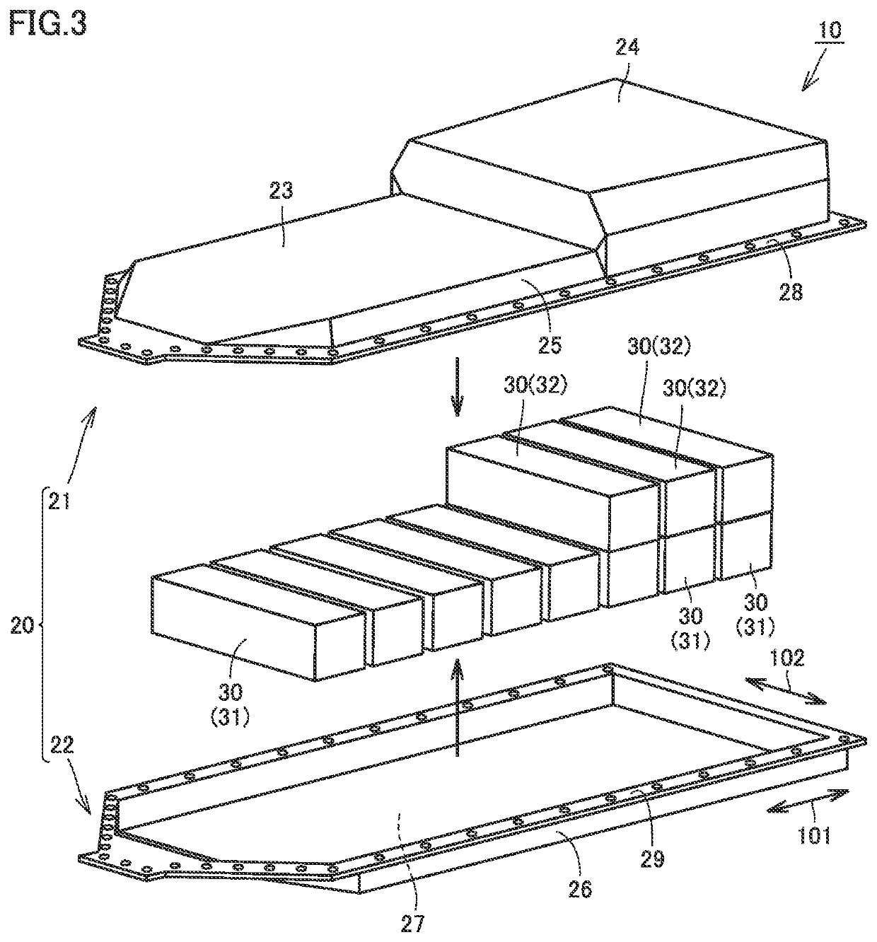
[0035]Lower case 22 has a box shape that is open upwardly. Lower case 22 has bottom portion 27 described above, a sidewall portion 26 and a flange portion 29. Bottom portion 27 is provided to face ceiling portion 23 in the up-down direction. Sidewall portion 26 is provided to extend upwardly from an outer peripheral edge of bottom portion 27. Sidewall portion 26 forms a sidewall of housing case 20, together with sidewall portion 25 of upper case 21. Flange portion 29 extends from an upper end of sidewall portion 26 to the outside of housing case 20, thereby forming a flange shape.

[0036]With flange portion 28 and flange portion 29 being stacked in the up-down direction, flange portion 28 and flange portion 29 are fastened by a plurality of fastening members (not shown). As a result, upper case 21 and lower case 22 are integrally coupled to each other and form a space for housing the plurality of cell stacks 30.

[0037]The plurality of cell stacks 30 have a plurality of first cell stack...


PUM


Abstract

A vehicle includes: a floor panel; and a battery pack mounted under the floor panel. The battery pack includes: a plurality of cell stacks; a housing case including a bottom portion and configured to house the plurality of cell stacks; and a plurality of support members provided on the bottom portion and spaced apart from one another. When a front region, a central region and a rear region are defined in a bottom view of the housing case, a ratio of a total area where the support member is provided in the central region to an area of the central region is higher than a ratio of a total area where the support member is provided in the rear region to an area of the rear region.

Description

[0001]This nonprovisional application is based on Japanese Patent Application No. 2018-054792 filed on Mar. 22, 2018 with the Japan Patent Office, the entire contents of which are hereby incorporated by reference.BACKGROUNDField[0002]The present disclosure generally relates to a vehicle, and more particularly to a vehicle having a battery pack mounted under a floor panel.Description of the Background Art[0003]For example, Japanese Patent Laying-Open No. 2011-126452 discloses a structure for attaching a battery for an electric powered vehicle mounted under a vehicle body floor.SUMMARY[0004]As disclosed in Japanese Patent Laying-Open No. 2011-126452 above, a vehicle having a battery pack mounted under a floor panel of the vehicle has been known.[0005]In such a vehicle, the battery pack interferes with, for example, a fallen object on a road surface or a height difference of a road surface, and is easily subjected to shock from the road surface. Therefore, it is conceivable to provide ...

Claims


Application Information

Patent Timeline
Patent Type & Authority Patents(United States)
IPC IPC(8): B60K1/04
CPCB60K1/04B60K2001/0438B62D21/09B62D21/15
Inventor WATANABE, HIROTAKAINOUE, SHIGEYUKIUCHIYAMA, TOSHIOINUKAI, SATOSHI
Owner TOYOTA JIDOSHA KK
Why Eureka
Try Eureka