Solid electrolytic capacitor

a technology of electrolytic capacitors and solids, applied in the direction of electrolytic capacitors, electrical equipment, capacitors, etc., can solve the problems of insufficient reduction of esr, damage to carbon fiber itself, inability to reduce esr, etc., and achieve the effect of reducing the resistance value and avoiding the deformation of the conducting polymer layer

Inactive Publication Date: 2012-07-10
SANYO ELECTRIC CO LTD
View PDF5 Cites 3 Cited by
  • Summary
  • Abstract
  • Description
  • Claims
  • Application Information

AI Technical Summary

Benefits of technology

[0013]In the above-described solid electrolytic capacitor, the conducting polymer layer contains the metal-based conductive filler in at least one of a flake form and a fiber form. Accordingly, the metal-based conductive fillers come in contact with each other in the conducting polymer layer, so that a conductive path can be formed in the conducting polymer layer. Thus, a resistance value of the conducting polymer layer can be reduced.
[0014]In addition, the metal-based conductive filler is more easily subjected to plastic deformation compared to a carbon-based conductive filler. Accordingly, the metal-based conductive filler can follow the deformation of the conducting polymer layer under a high-temperature condition and does not cause a gap between the conducting polymer and the metal-based conductive filler or damage to the metal-based conductive filler. Furthermore, the considerable deformation of the conducting polymer layer caused under a high-temperature condition can be suppressed by containment of the metal-based conductive filler. Accordingly, separation is prevented at the interface between the conducting polymer layer and the dielectric layer. Thus, changes of capacitance in storage at a high-temperature can be reduced, and thereby reliability can be increased.
[0015]Here, it is preferable that the metal-based conductive filler be contained overall in a thickness direction of the conducting polymer layer. Thereby, the metal-based conductive filler can be dispersed overall in the thickness direction of the conducting polymer layer, so that a resistance value of the conducting polymer layer can be further reduced.
[0016]In addition, it is preferable that a content of the metal-based conductive filler in the conducting polymer layer be in a range from 1 weight % to 70 weight %. Setting the content in the above-described range enables the metal-based conductive filler to securely come in contact with each other in the conducting polymer layer. Accordingly, a resistance value of the conducting polymer layer can be further reduced, and thus ESR can be further reduced.
[0017]As described above, one embodiment of the invention can provide a solid electrolytic capacitor with low ESR and excellent reliability in high-temperature storage.

Problems solved by technology

Thus, ESR cannot be reduced greatly.
Consequently, there arise problems such as a gap generated between the conducting polymer and the carbon fiber, and damage to the carbon fiber itself.
As a result, ESR cannot be sufficiently reduced even if the conducting polymer layer contains the carbon fiber.

Method used


Image

  • Solid electrolytic capacitor
  • Solid electrolytic capacitor
  • Solid electrolytic capacitor

Examples


example

[0046]A solid electrolytic capacitor according to the invention will be described below by specific examples. However, the invention is not limited to the following examples.

Preliminary Experiment

[0047]A chemical polymerization solution is prepared by dissolving 10 weight % of pyrrole as a polymerizable monomer and 16 weight % of para-toluene sulfonic acid iron (III) as a dopant / oxidizing agent in a mixed solvent of ethanol and water with a volume ratio of 5 to 1. Then, 7.5 weight % of a flake-form silver filler, as a metal-based conductive filler, with a mean flake diameter of 10 μm and a mean aspect ratio of 50 is uniformly mixed in this chemical polymerization solution. Thereafter, a glass substrate is soaked in and taken out from the chemical polymerization solution. This glass substrate is left in the atmosphere for two hours. Thereby, a conducting polymer film with a thickness of approximately 100 μm is formed on the glass substrate.

[0048]After that, the conducting polymer fil...

experiment 1

Example 1

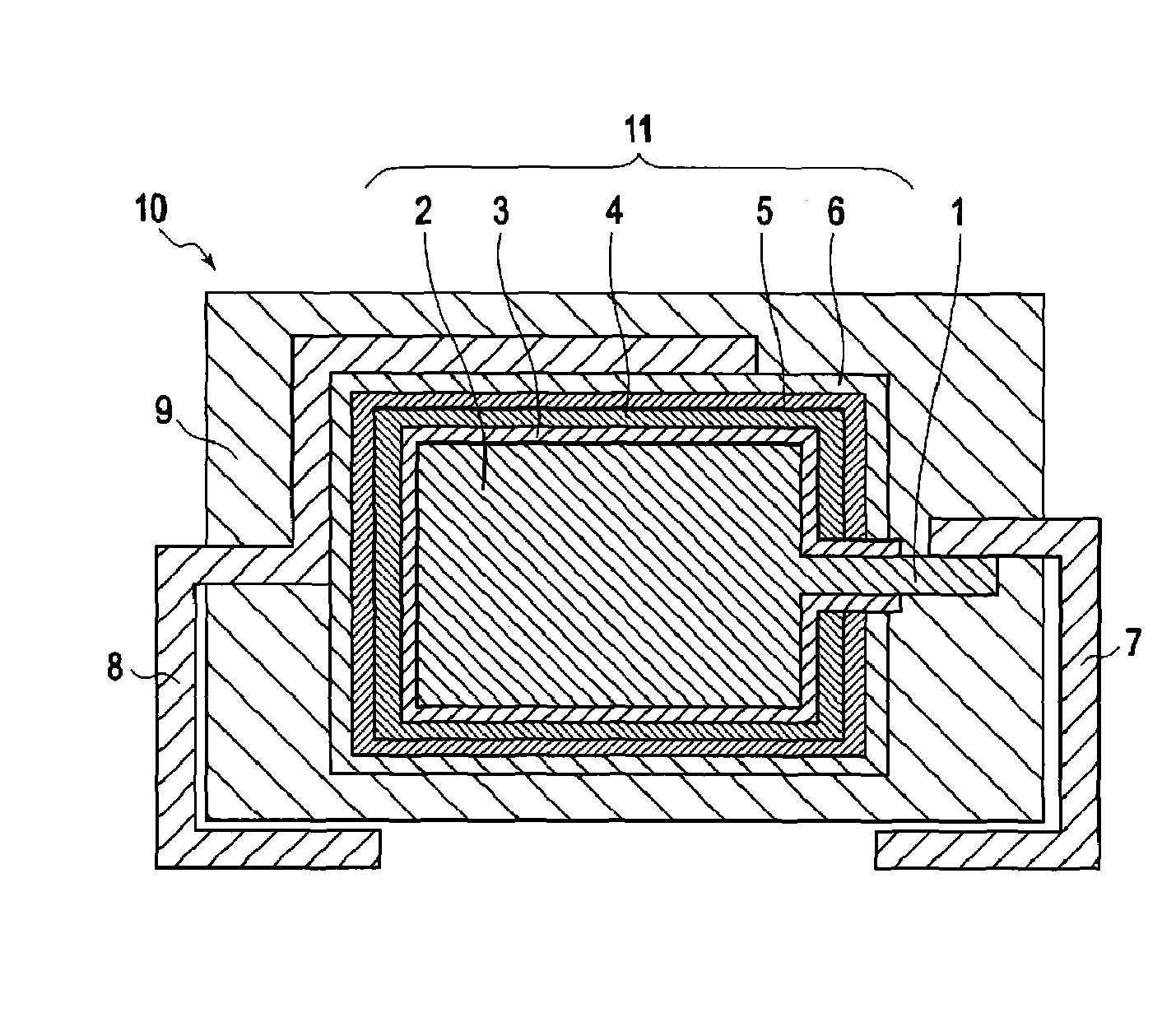
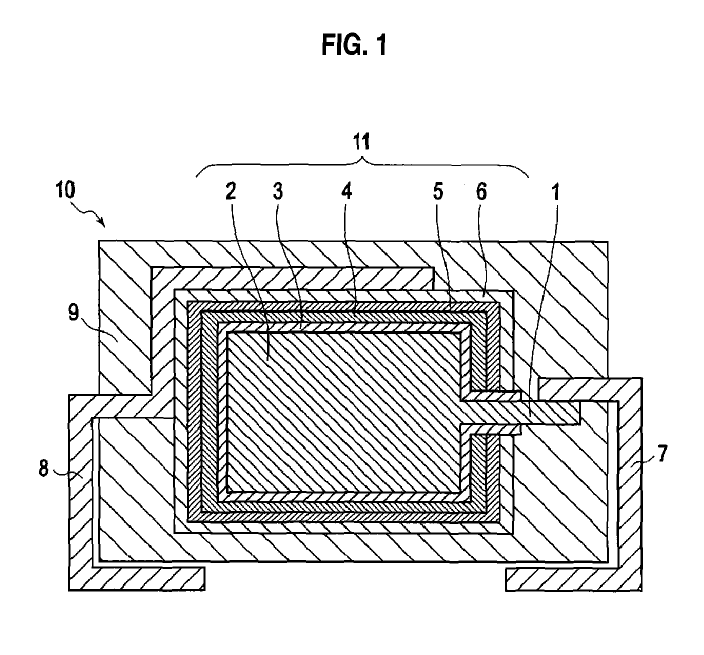
[0049]A tantalum powder with a mean particle diameter of approximately 2 μm is formed in a substantially plate-shape on anode lead wire 1 formed of tantalum so as to cover one portion of anode lead wire 1, and then is sintered in vacuum to form anode 2. Subsequently, anode 2 is anodized at a specific voltage of approximately 8 V for 10 hours in a phosphoric acid solution with a concentration of approximately 0.1 weight % and at a temperature being kept at approximately 60° C. Thereby, dielectric layer 3 formed of tantalum oxide is formed so as to surround the circumference of anode 2.

[0050]Next, a chemical polymerization solution is prepared by dissolving 10 weight % of pyrrole as a polymerizable monomer and 16 weight % of para-toluene sulfonic acid iron (III) as a dopant / oxidizing agent in a mixed solvent of ethanol and water with a volume ratio of 5 to 1. Then, 5 weight % of a flake-form silver filler, as a metal-based conductive filler, with a mean flake diameter of 10 μ...

example 2

[0052]As a metal-based conductive filler, a solid electrolytic capacitor is manufactured in a similar manner as that of example 1, except that a fiber-form copper filler with a mean fiber diameter of 0.5 μm and a mean fiber length of 30 μm is used.


PUM

PropertyMeasurementUnit
diameteraaaaaaaaaa
diameteraaaaaaaaaa
diameteraaaaaaaaaa

Abstract

Provided is a solid electrolytic capacitor with low ESR (equivalent series resistance) and excellent reliability during high-temperature storage. The solid electrolytic capacitor includes an anode formed of a valve metal, a dielectric film provided on the anode, a conducting polymer layer provided on the dielectric layer, and a cathode extraction layer provided on the conducting polymer layer. The conducting polymer layer contains a metal-based conductive filler in at least one of a flake form and a fiber form.

Description

CROSS REFERENCE TO RELATED APPLICATIONS[0001]This application claims priority based on 35 USC 119 from prior Japanese Patent Application No. P2007-216059 filed on Aug. 22, 2007, the entire contents of which are incorporated herein by reference.BACKGROUND OF THE INVENTION[0002]1. Field of the Invention[0003]The present invention relates to a solid electrolytic capacitor including an anode formed of a valve metal as well as a dielectric film, a conducting polymer layer, and a cathode extraction layer deposited thereon.[0004]2. Description of Related Art[0005]Solid electrolytic capacitors are used in a manner of being incorporated into power supply circuits of CPU and peripheral circuits thereof in various kinds of mobile information terminals, such as personal computers and mobile phones, various kinds of image information devices, such as digital cameras, and other electronic devices.[0006]In general, in a solid electrolytic capacitor, a dielectric layer is formed on an anode made of...

Claims


Application Information

Patent Timeline
Patent Type & Authority Patents(United States)
IPC IPC(8): H01G9/00H01G9/02
CPCH01G9/0425
Inventor OTA, TAEKOFUJITA, MASAYUKIUMEMOTO, TAKASHINONOUE, HIROSHI
Owner SANYO ELECTRIC CO LTD
Why Eureka
Try Eureka