
Device for applying a foamed treating material under pressure to a traveling sheet of textile yarn

a technology of textile yarn and treating material, applied in textile treatment with treating outlet, transportation and packaging, indefinite length material liquid/gas/vapor treatment, etc., can solve the problems of increasing wastewater and uneven distribution of treating material throughout the substrate, and achieve the effect of minimizing surface abrasion

Active Publication Date: 2020-07-07
GASTON SYST INC
View PDF10 Cites 1 Cited by
  • Summary
  • Abstract
  • Description
  • Claims
  • Application Information

AI Technical Summary

Benefits of technology

[0005]The present invention provides a different approach to preventing or limiting the escape of unapplied treating material and the seepage of treating material from space to space, thereby limiting undesirable wastewater and uneven distribution of the treating material. Rather than compressing the substrate, which is not of appreciable benefit when treating sheets of non-compressible yarns, the present invention obtains advantageous results by applying a resiliently compressible soft rubber opposing member that itself compresses to seal spaces in the yarns and prevent seepage of treating material between spaces that would otherwise disrupt uniform distribution of the treating material.
[0008]To prevent escape of treating material from the end portions of the nozzle slot that extend beyond the widthwise extent of the sheet of yarns, end seals are preferably mounted in the end portions of the nozzle slot, and the drive roll and resilient exterior layer extend laterally beyond the width of the sheet of yarns and over at least a portion of the end seals.
[0010]To minimize abrasion of the surface of the resilient exterior layer during contact of the layer with the leading and trailing surfaces of the nozzle, a lubricant dispenser is mounted on the device in contact with the surface of the exterior layer. The lubricant dispenser includes an elongated strip of sponge-like wicking material extending along the length of the exterior layer in lubricant dispensing contact with the surfaces of the nozzle.

Problems solved by technology

On the other hand, yarns in a sheet of yarns do not appreciably compress and spacing occurring from separation of yarns and yarn crossovers occurring during travel of the sheet of yarns are pronounced and extend through the sheet from one surface to the other, allowing the foam or resulting liquid to pass directly through the substrate more freely and escape from the substrate, creating increased wastewater, and passing into adjacent spaces, resulting in uneven distribution of the treating material throughout the substrate.

Method used


Image

  • Device for applying a foamed treating material under pressure to a traveling sheet of textile yarn
  • Device for applying a foamed treating material under pressure to a traveling sheet of textile yarn
  • Device for applying a foamed treating material under pressure to a traveling sheet of textile yarn

Examples


Embodiment Construction

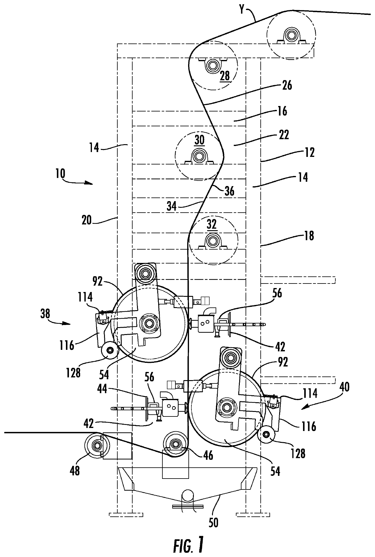
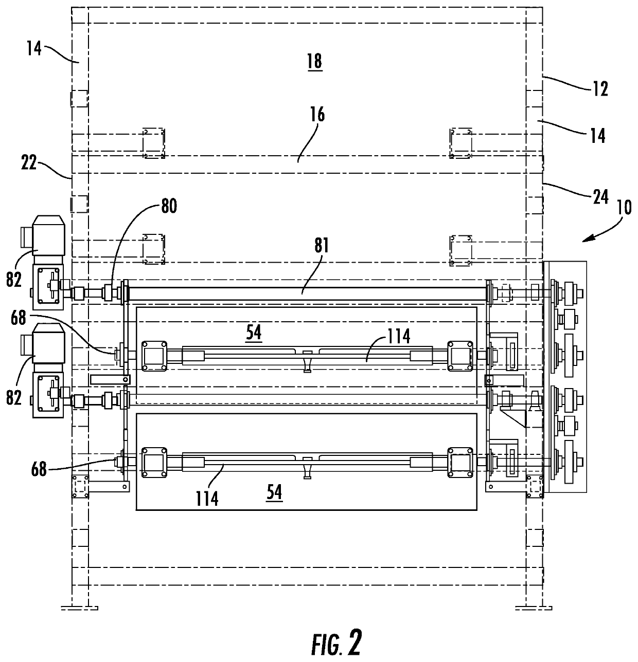
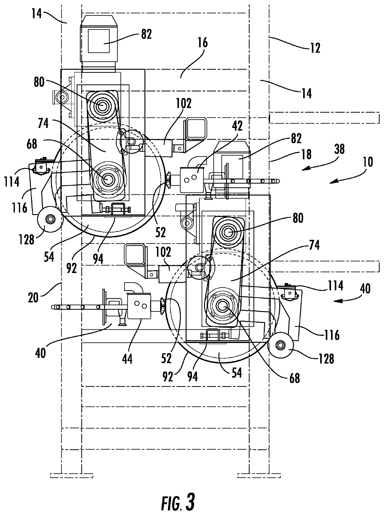
[0023]The device 10 of the preferred embodiment of the present invention illustrated in the drawings includes an upstanding frame 12 having vertical corner posts 14 joined by horizontal cross bars 16, thereby defining a front 18, a rear 20, and connecting sides 22, 24. The front 18 and rear 20 are of a widthwise extent greater than the widthwise extent of a sheet S of textile yarns 26 traveling vertically downwardly through the frame 12 generally parallel with and spaced inwardly of the front 18 of the frame.

[0024]Mounted on the cross bars 16 in the upper portion of the frame 12 are three vertically spaced rotatable guide rolls 28, 30, 32, aligned with the path of the traveling sheet S of yarns 26. The first and third guide rolls 28 and 32 tangentially engage one side surface 34 of the traveling sheet S of yarns 26. The second guide roll 30 is between the first and third rolls and horizontally offset for engagement with the opposite side surface 36 of the travelling sheet S of yarns...


PUM

PropertyMeasurementUnit
pressureaaaaaaaaaa
compressibleaaaaaaaaaa
diameteraaaaaaaaaa

Abstract

A device for applying a foamed treating material under pressure to a traveling sheet of relatively incompressible textile yarns. A foam applicator unit has a nozzle with a foam dispensing slot facing across one side of the traveling sheet of yarns. A drive roll faces the other side of the traveling sheet of yarns in tangential alignment with the foam dispensing slot. The roll has a resiliently compressible, soft rubber outer layer, which compresses to conform with the surface of the relatively incompressible yarns and presses the traveling sheet of yarns against the applicator surfaces leading to and away from the slot to prevent escape of foam and to prevent passage of foam between yarns to maintain uniform distribution of foam applied to the traveling sheet of yarns.

Description

FIELD OF THE INVENTION[0001]The present invention relates to applying foamed treating material under pressure to a traveling sheet of textile yarns, and, more particularly, to preventing unwanted escape of pressurized foamed treating material as the material is being applied to sheet of yarns and preventing transfer of such pressurized foamed treating material between spaces in yarns, and preventing transfer of such pressurized foamed treating material between spaces in yarns in the sheet of yarns.BACKGROUND OF THE INVENTION[0002]It is common in the textile industry to apply treating material, such as, for example, dye or sizing to sheets of textile material either by transporting the sheets of textile material through a bath or baths containing treating material in liquid form, or, now more preferably, applying the treating material in a foamed form by an applicator or applicators that dispense the foam into or onto the surface or surfaces of the sheets of traveling textile substra...

Claims


Application Information

Patent Timeline
Patent Type & Authority Patents(United States)
IPC IPC(8): B05C5/02B65H51/12D06B5/08D06B1/08D06B1/00B65H57/14D06B23/02
CPCD06B1/00B05C5/0245B05C5/0254B65H57/14D06B1/08B65H51/12D06B5/08D06B23/021B65H2701/31D06B19/0094
Inventor AURICH, CHRISTOPH W.TALBERT, JR., JAMES E.MORGAN, JERRY D.
Owner GASTON SYST INC
Learn More