Highway crash barrel

a technology of crash barrel and high-speed transmission, which is applied in the direction of roadway safety arrangements, roadways, construction, etc., can solve the problems of difficult stacking, costly and dangerous cleanup, and difficult handling and separation, and achieves convenient stacking, structural rigidity, and enhanced strength.

Active Publication Date: 2020-07-14
VAUGHAN JR EARL
View PDF19 Cites 2 Cited by
  • Summary
  • Abstract
  • Description
  • Claims
  • Application Information

AI Technical Summary

Benefits of technology

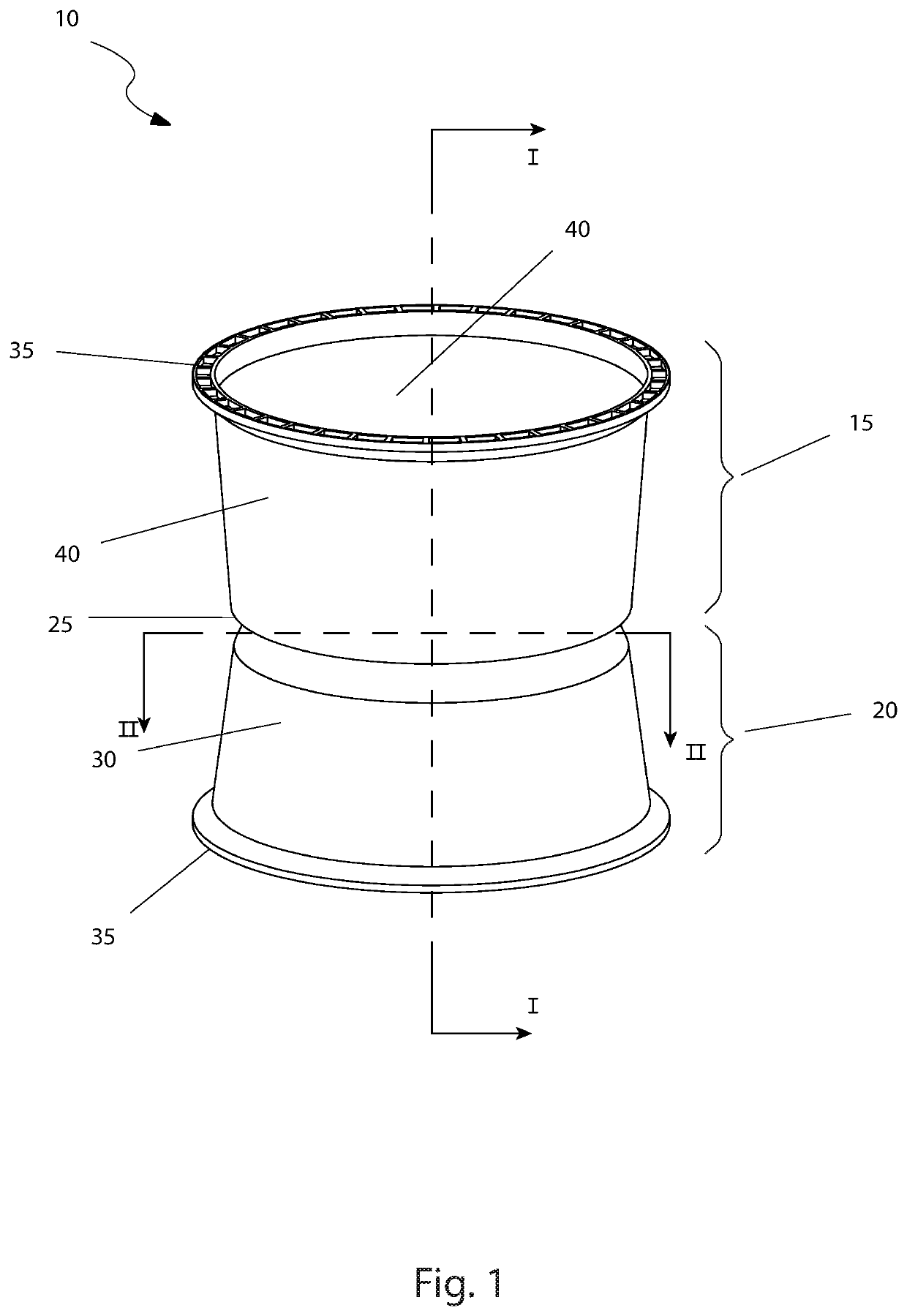
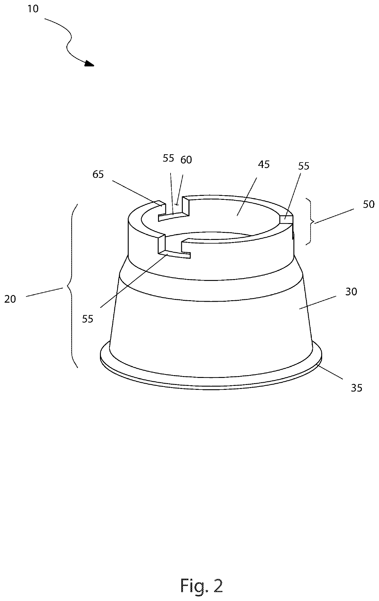
[0005]The lower barrel half may be made from high density polyethylene plastic along with a first one or more ultraviolet inhibitors that are retro-reflective. The lower barrel half and the upper barrel half may be stacked and utilize tapered sides that facilitate stacking when empty. The upper barrel half may be made from high density polyethylene plastic along with a second one or more ultraviolet inhibitors that are retro-reflective. The upper barrel half and the lower barrel half may be provided with a reinforced flared rim to enhance strength and provide structural rigidity. An upper portion of the lower barrel half may be provided with a male flange which interlocks with the upper barrel half. The male locking tabs may be provided on the upper surface of the male flange to facilitate interlocking. The three male locking tabs are arranged at one-hundred-twenty degrees from each other. Each of the male locking tab includes a male open slot and a male locking arm. Each of the male locking tab may also be symmetrical to their counterparts and allow for matching the lower barrel half and the upper barrel half at any one-hundred-twenty-degree segment.
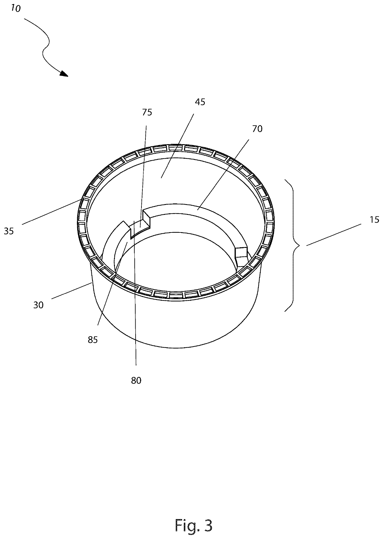
[0006]The upper barrel half may be filled with a second ballast to increase overall mass of the safety crash barrel to aid in stopping wayward motor vehicles. The second ballast may be selected from the group consisting of sand, water, or other high-density material. The upper barrel half may include a female flange and a reinforced flared rim in the open interior. The female flange is provided with three female locking tabs. Each female locking tab is arranged at one-hundred-twenty degrees to each other. Additionally, each female locking tab may also include a female open slot and a female locking arm. During engagement of the upper barrel half with the lower barrel half, an individual the male locking tab engages with an individual the female locking tab, accomplished by placing the female locking arm under the male locking arm and rotating in place by five degrees. The safety crash barrel may be forty-eight inches high with a maximum diameter of thirty inches.

Problems solved by technology

While such barrels work well, they are difficult to handle and stack due to their large size.
Even after they are stacked, they are difficult to separate due to the vacuum that is formed between the components.
Additionally, should lids come off, or bottoms fails, the contained material can spill all over adjacent road surfaces resulting in costly and dangerous cleanup.

Method used


Image

  • Highway crash barrel
  • Highway crash barrel
  • Highway crash barrel

Examples


Embodiment Construction

[0029]The best mode for carrying out the invention is presented in terms of its preferred embodiment, herein depicted within FIGS. 1 through 5. However, the invention is not limited to the described embodiment, and a person skilled in the art will appreciate that many other embodiments of the invention are possible without deviating from the basic concept of the invention and that any such work around will also fall under scope of this invention. It is envisioned that other styles and configurations of the present invention can be easily incorporated into the teachings of the present invention, and only one (1) particular configuration shall be shown and described for purposes of clarity and disclosure and not by way of limitation of scope. All of the implementations described below are exemplary implementations provided to enable persons skilled in the art to make or use the embodiments of the disclosure and are not intended to limit the scope of the disclosure, which is defined by...


PUM


Abstract

A highway crash barrel incorporates a first portion and a second portion capable of interlocking with each other. A ballast is present in the first portion and a hollow portion is present in the second portion.

Description

FIELD OF THE INVENTION[0001]The present invention relates to a highway crash barrel.BACKGROUND OF THE INVENTION[0002]Street and highway safety is at the forefront of concerns when speaking in regards to public safety. One type of system that is frequently used to avoid accidents and reduce death tolls are vehicle barrier systems. These are mechanical system that rely on absorbing impact energy itself rather than passing it the impacting vehicle and its occupants. A common type of system utilizes barrels filled with sand, water, or other material to perform this task.[0003]While such barrels work well, they are difficult to handle and stack due to their large size. Even after they are stacked, they are difficult to separate due to the vacuum that is formed between the components. Additionally, should lids come off, or bottoms fails, the contained material can spill all over adjacent road surfaces resulting in costly and dangerous cleanup. Accordingly, there exists a need for a means ...

Claims


Application Information

Patent Timeline
Patent Type & Authority Patents(United States)
IPC IPC(8): E01F9/00E01F9/654E01F9/688
CPCE01F9/688E01F9/654E01F15/146
Inventor VAUGHAN, JR., EARL
Owner VAUGHAN JR EARL
Why Eureka
Try Eureka