
Optical module for optical height measurement

a technology of optical height measurement and optical module, which is applied in the direction of instruments, optical beam sources, interferometers, etc., can solve the problems of failure to generate the normal focus error signal, and achieve the effect of high accuracy detection

Active Publication Date: 2020-07-28
HITACHI-LG DATA STORAGE
View PDF5 Cites 0 Cited by
  • Summary
  • Abstract
  • Description
  • Claims
  • Application Information

AI Technical Summary

Benefits of technology

The present invention provides an optical module that can accurately measure the height of a surface with any layer structure, including transparent or semi-transparent thin films. This ensures highly accurate detection of the surface height of a specimen with any shape.

Problems solved by technology

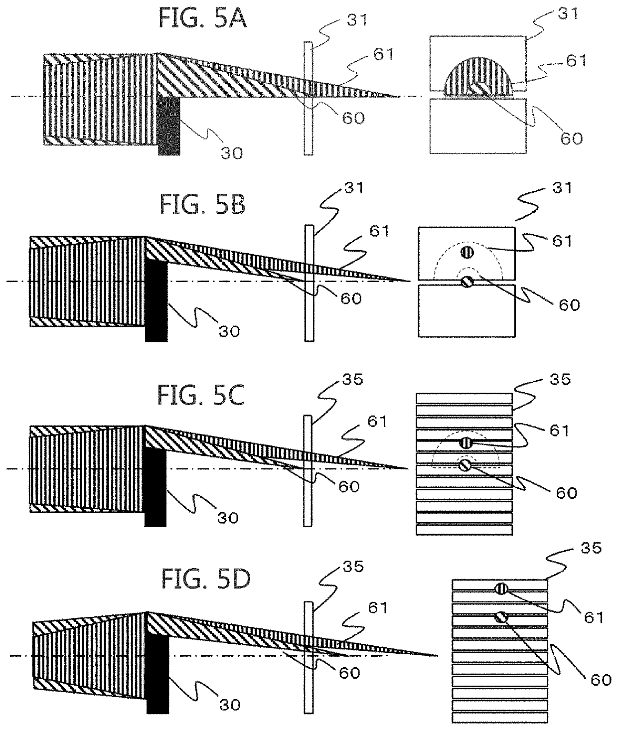
However, in the case where the specimen has a layer structure including a semi-transparent thin film, a reflected light from the specimen surface interferes with a reflected light from the layered structure, possibly failing to generate the normal focus error signal.
However, in the case where the layered structure is not a normalized layered structure like an optical disk but is any given layered structure, there may be a case where entering of the stray light from the other layer into a light-receiving surface causes a failure to generate a normal focus error signal.

Method used


Image

  • Optical module for optical height measurement
  • Optical module for optical height measurement
  • Optical module for optical height measurement

Examples


example

[0024]This example describes the case where, in an optical module for optical height measurement that can highly accurately detect only a surface height of a specimen having any shape, the specimen has a layered structure including a transparent or semi-transparent film.

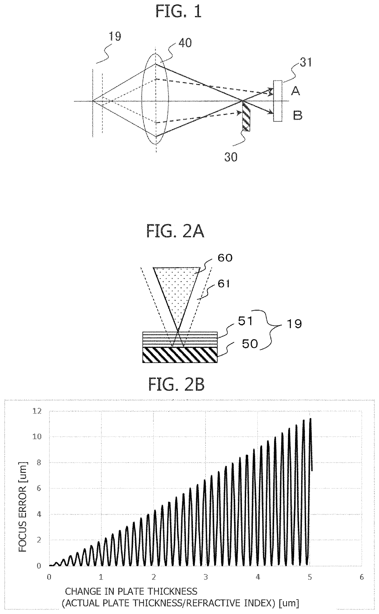
[0025]First, the following describes a principle of optically measuring the height of the specimen. FIG. 1 is a conceptual diagram describing a method that irradiates the specimen with a light beam and measures the height of the specimen from the reflected light using a knife-edge method. In FIG. 1, reference numeral 30 denotes a knife-edge, reference numeral 40 denotes an objective lens, and reference numeral 19 denotes a specimen. FIG. 1 illustrates a configuration where a feedback light of a light with which the specimen 19 is irradiated by the objective lens 40 is received by a two-divided optical detector 31. In the case where the knife-edge 30 is at a focal surface below an optical axis, when the surface of the...


PUM

PropertyMeasurementUnit
wavelengthaaaaaaaaaa
optical height measurementaaaaaaaaaa
surface heightaaaaaaaaaa

Abstract

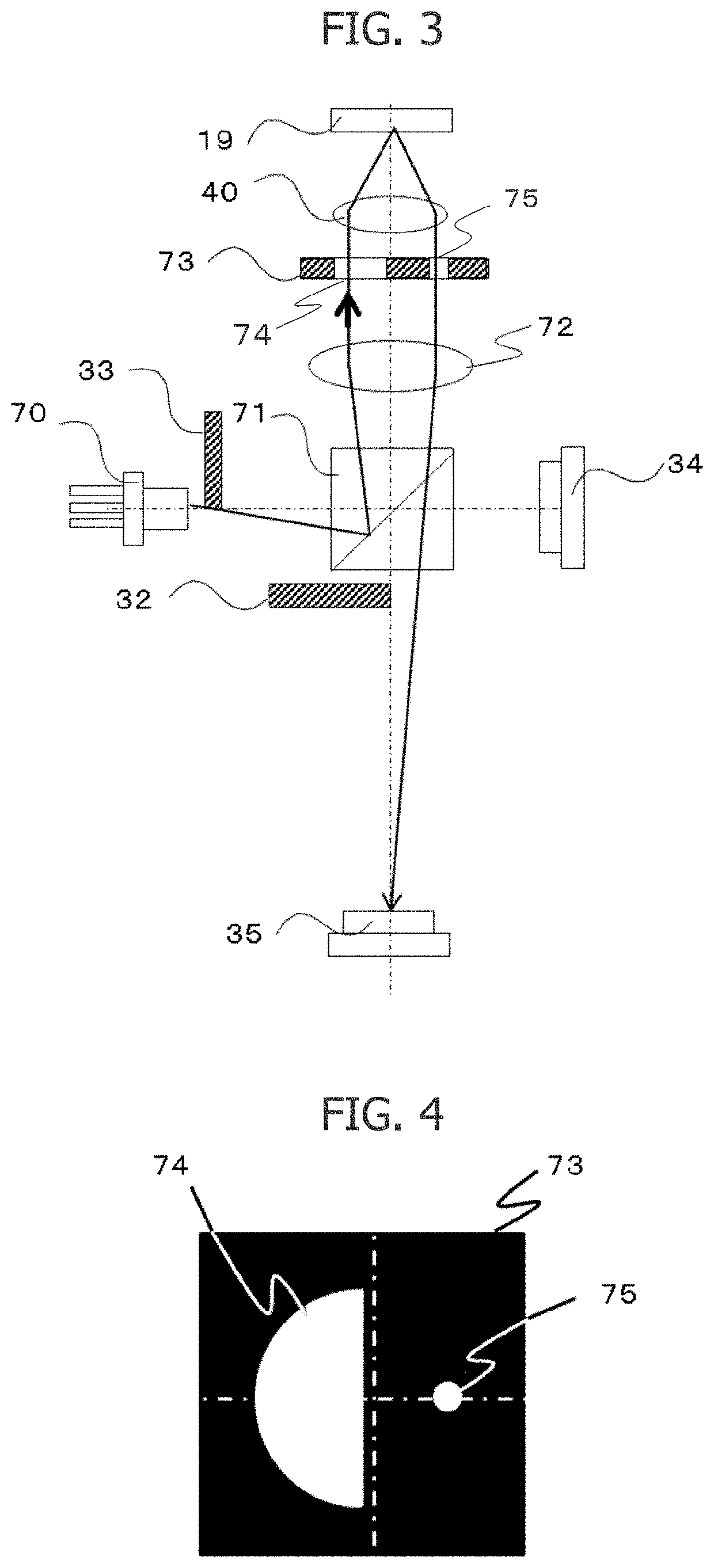
The optical module for optical height measurement includes a laser light source, an irradiation optical system, a detection optical system, and a detector. The laser light source is configured to irradiate the layer-structured specimen with a light beam. The irradiation optical system includes an objective lens. The objective lens is located to be approximately perpendicular to the layer-structured specimen. The detection optical system is configured to guide a reflected light reflected by the layer-structured specimen and a light passing through the objective lens and an aperture-restrictor-for-return to the detector. The aperture-restrictor-for-return is located immediately after the objective lens. The aperture-restrictor-for-return is configured to restrict the reflected light and cause only a light in a high NA region to pass through. The detector is configured to convert an entered light into a light detection signal. The detector includes a multi-divided detector array.

Description

CROSS-REFERENCE TO RELATED APPLICATION[0001]The present application claims priority from Japanese application JP 2018-055893, filed on Mar. 23, 2018, the contents of which is hereby incorporated by reference into this application.BACKGROUND[0002]The present invention relates to an optical module for optical height measurement that optically measures a surface height of a layer-structured specimen including a transparent or semi-transparent thin film.[0003]There has been known a focus control signal used for an optical disk device that is used to highly accurately focus an optical disk as a specimen. Japanese Patent Application Laid-Open No. 9-265722 discloses a state in which the focus control signal changes according to a change in shift amount of a focal position to the specimen.[0004]Japanese Patent Application Laid-Open No. 2008-102998 discloses an optical system for a multilayer optical disk that avoids a stray light from another layer and does not give an influence to a focus ...

Claims


Application Information

Patent Timeline
Patent Type & Authority Patents(United States)
IPC IPC(8): G01B9/02G01B11/06G02B27/09
CPCG01B11/0608G02B27/0955G01B9/02015G02B27/0977G01B2290/45G01B11/0616G11B7/09G11B7/127G11B7/131
Inventor TOMITA, DAISUKESUENAGA, HIDEOKUROKAWA, TAKAHIROMORIMOTO, YOSHITAKA
Owner HITACHI-LG DATA STORAGE
Learn More