
Amplitude detection apparatus

a detection apparatus and amplitude technology, applied in the direction of amplitude demodulation, pulse characteristics measurement, instruments, etc., can solve the problems of error increasing between the maximum the minimum value obtained from digital signals and the actual sine wave, so as to achieve the effect of high-precision detection of waveform signals

Inactive Publication Date: 2011-08-16
TOSHIBA MASCH CO LTD
View PDF12 Cites 0 Cited by
  • Summary
  • Abstract
  • Description
  • Claims
  • Application Information

AI Technical Summary

Benefits of technology

The present invention relates to an amplitude detection apparatus for detecting the amplitude of a waveform signal. The apparatus includes a maximum-minimum value detector, two lowpass filters, a cycle detector, a correction coefficient generator, and two multipliers. The apparatus can accurately detect the amplitude of a waveform signal even if the cycle of the waveform signal is small. The technical effect of the invention is to provide a reliable and accurate method for detecting the amplitude of a waveform signal.

Problems solved by technology

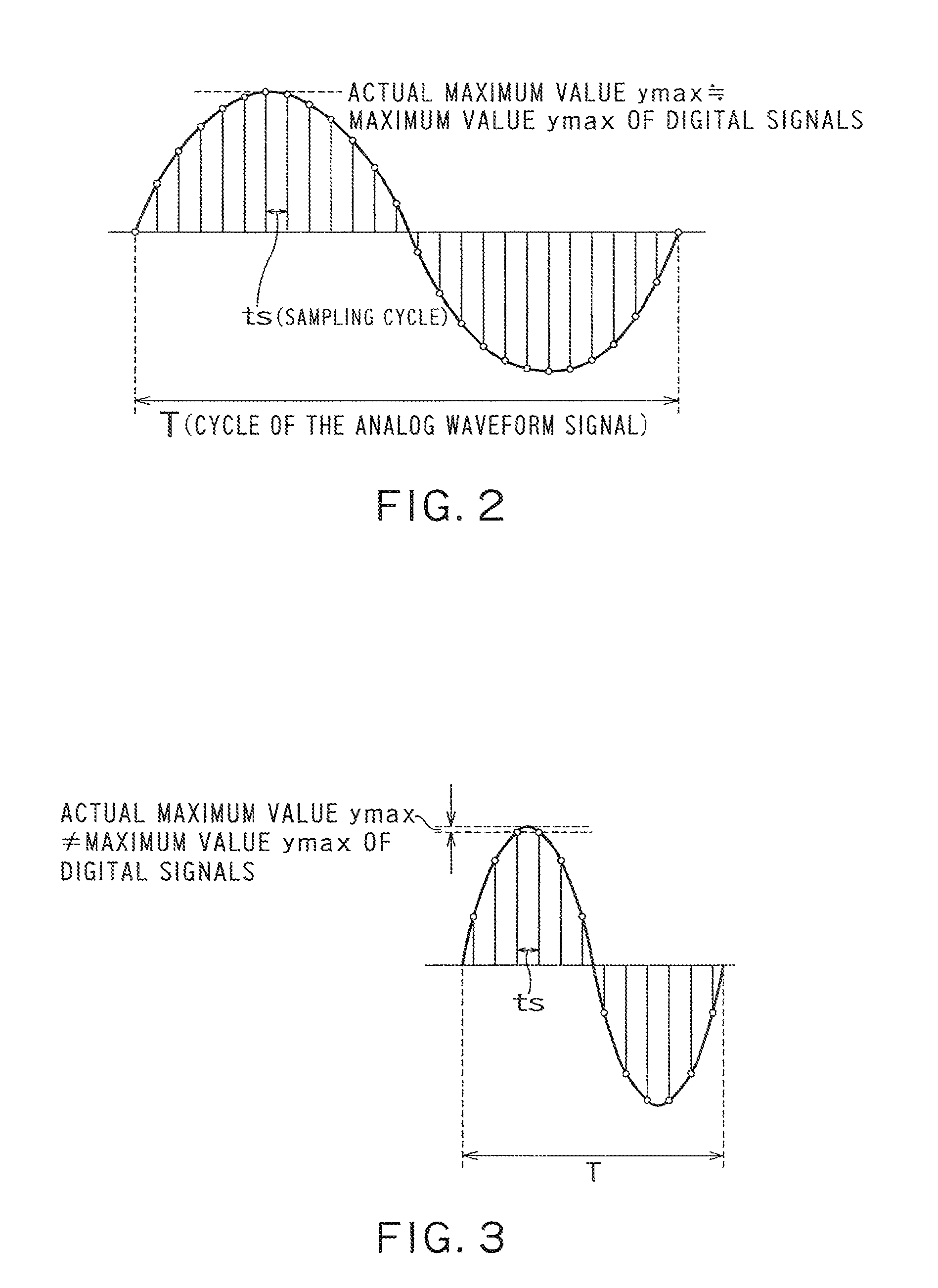
However, if the sine wave cycle is shortened to thereby reduce a difference between the sine wave cycle and the sampling cycle, it is highly likely that an error increases between the maximum value obtained from the digital signals and that of the actual sine wave and an error increases between the minimum value obtained from the digital signals and that of the actual sine wave.

Method used


Image

  • Amplitude detection apparatus
  • Amplitude detection apparatus
  • Amplitude detection apparatus

Examples


Embodiment Construction

[0033]Embodiments of the present invention will be explained below in detail with reference to the accompanying drawings. Note that the invention is not limited thereto.

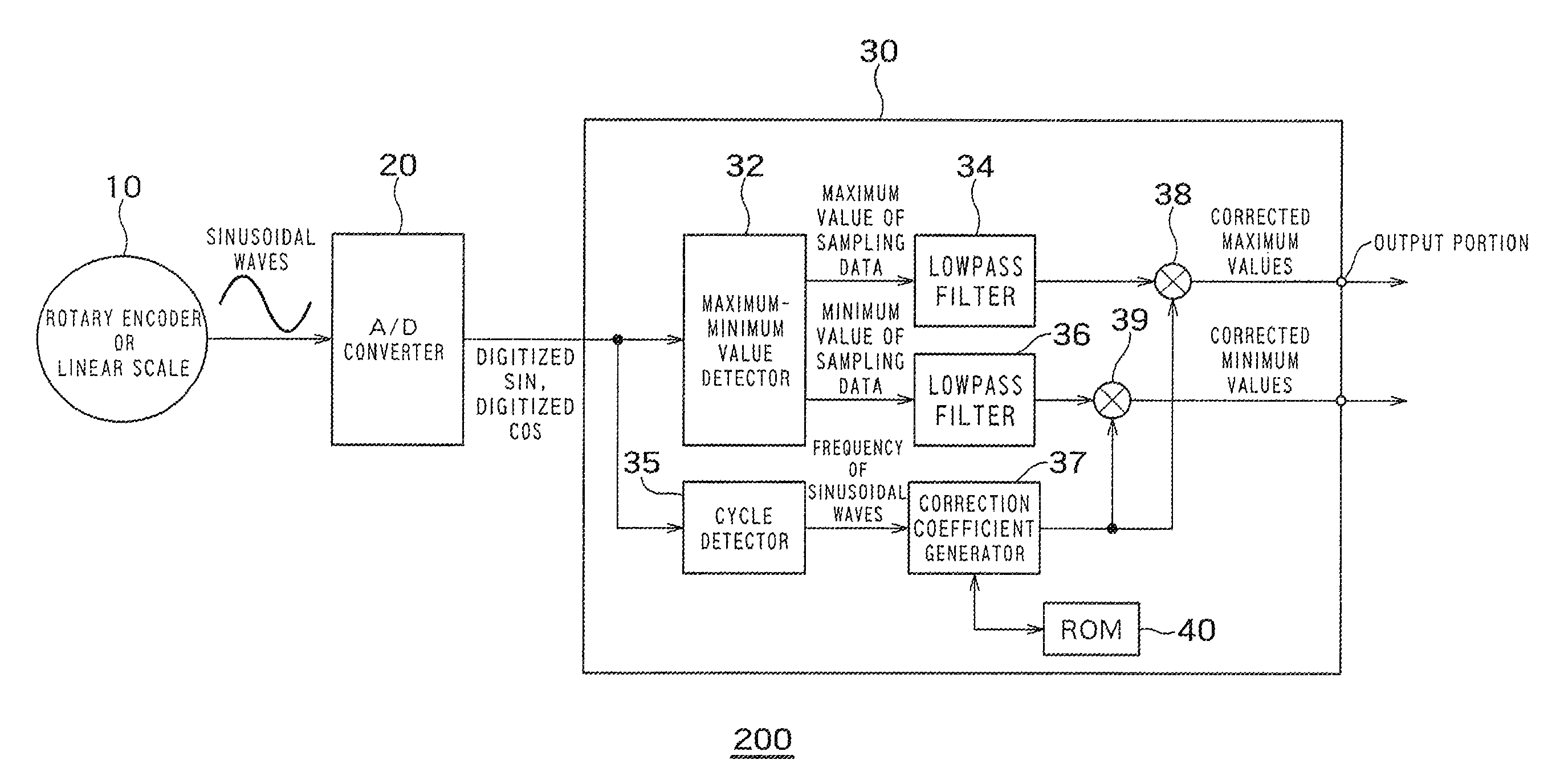
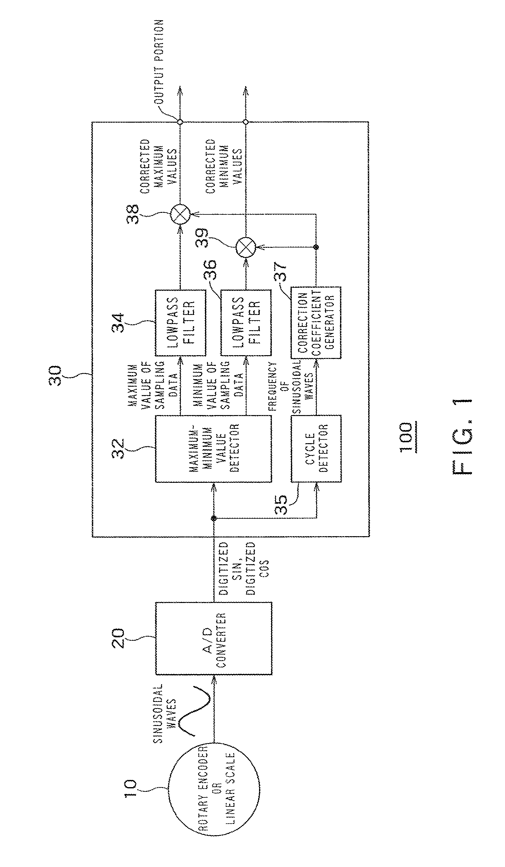
[0034]FIG. 1 is a block diagram of a position detection apparatus 100 according to an embodiment of the present invention. The position detection apparatus 100 includes a rotary encoder or a linear scale 10, an A / D converter 20f and an amplitude detection apparatus 30. The amplitude detection apparatus 30 is a general-purpose CPU or a logic LSI. As the amplitude detection apparatus 30, a custom LSI such as an FPGA (Field Programmable Gate Array) or an ASIC (Application Specific Integrated Circuit) can be used. If the amplitude detection apparatus 30 is realized as a logic circuit on the LSI, it is possible to perform a repetition process for repeatedly performing the same process in a short time. Alternatively, the amplitude detection apparatus 30 can be realized by the general-purpose CPU and software. If the amplit...


PUM


Abstract

This disclosure concerns an amplitude detector comprising: a maximum-minimum detector detecting a maximum and a minimum values of a digital signals; a first and a second lowpass filters respectively having a cutoff frequency lower than a frequency of the waveform signal; a cycle detector detecting a cycle of the waveform signal; a correction coefficient generator generating a numeric value of a correction coefficient expressed by a calculation with respect to the cycle of the waveform signal and a cycle of the sampling; a first multiplier generating a corrected maximum value by multiplying the maximum value of the digital signals by the correction coefficient; a second multiplier generating a corrected minimum value by multiplying the minimum value of the digital signals by the correction coefficient; and an output portion outputting the corrected maximum value or an absolute value of the corrected minimum value as the amplitude of the waveform signal.

Description

CROSS-REFERENCE TO RELATED APPLICATION[0001]This application is based upon and claims the benefit of priority from the prior Japanese Patent Applications No. 2007-20031, filed on Jan. 30, 2007, the entire contents of which are incorporated herein by reference.BACKGROUND OF THE INVENTION[0002]1. Field of the Invention[0003]The present invention relates to an amplitude detection apparatus, and, for example, relates to an amplitude detection apparatus incorporated in a machine angle detector or a machine position detector.[0004]2. Related Art[0005]Generally, a rotary encoder is used as a position detector detecting a position of a moving body (e.g., a servo motor) making a rotational movement, or a linear scale is used as a position detector detecting a position of a moving body (e.g., a robot arm) making a linear reciprocating movement for accurately controlling movement of the machine. An output signal from the position detector is periodically subjected to analog-digital conversion ...

Claims


Application Information

Patent Timeline
Patent Type & Authority Patents(United States)
IPC IPC(8): H04L27/06
CPCH03D1/00G01R29/00G01R29/02G01R23/00
Inventor AONO, RYUJI
Owner TOSHIBA MASCH CO LTD
Learn More