Hydraulic block and manufacturing method for a hydraulic block including at least one check valve

a technology of hydraulic block and check valve, which is applied in the direction of brake components, vehicle sub-unit features, braking systems, etc., can solve the problem of at least one check valve being additionally used to achieve flow-optimized lift limitation, and achieve cost-effective execution

Active Publication Date: 2020-08-04
ROBERT BOSCH GMBH
View PDF11 Cites 0 Cited by
  • Summary
  • Abstract
  • Description
  • Claims
  • Application Information

AI Technical Summary

Benefits of technology

[0004]The present invention provides cost-effective hydraulic blocks each including at least one function-optimized check valve. Due to the direct attachment of the valve seat in the check valve receiving bore, which is formed as a stepped recess in the particular hydraulic block, a subassembly is not required to form the at least one check valve. Instead, the valve seat and the valve body of each check valve are / will be installed directly in the associated check valve receiving bore / the hydraulic block. A number of conventional check valve components which induce turbulences is reduced with the aid of the omission of the subassembly. In particular, it is ensured that the desired volume flow through the particular check valve (for example, for the aspiration / subsequent snifting of volume from a brake fluid reservoir) is not obstructed by a cage. As a result of the stepped design of the check valve receiving bore, a flow-optimized lift limitation in the at least one check valve is additionally achieved.
[0020]In one advantageous specific embodiment of the manufacturing method, before the introduction of the valve body and the fastening of the valve seat, the valve body is suctioned against the valve seat with the aid of a stamp, a leak-tightness of a contact between the valve body and the valve seat being checked at the same time. A presence of a flaw on the valve body or on the valve seat which prevents the desired liquid-tight contact between the valve body and the valve seat may thus be detected early and with the aid of a method step which is executable cost-effectively.

Problems solved by technology

As a result of the stepped design of the check valve receiving bore, a flow-optimized lift limitation in the at least one check valve is additionally achieved.

Method used


Image

  • Hydraulic block and manufacturing method for a hydraulic block including at least one check valve
  • Hydraulic block and manufacturing method for a hydraulic block including at least one check valve
  • Hydraulic block and manufacturing method for a hydraulic block including at least one check valve

Examples


Embodiment Construction

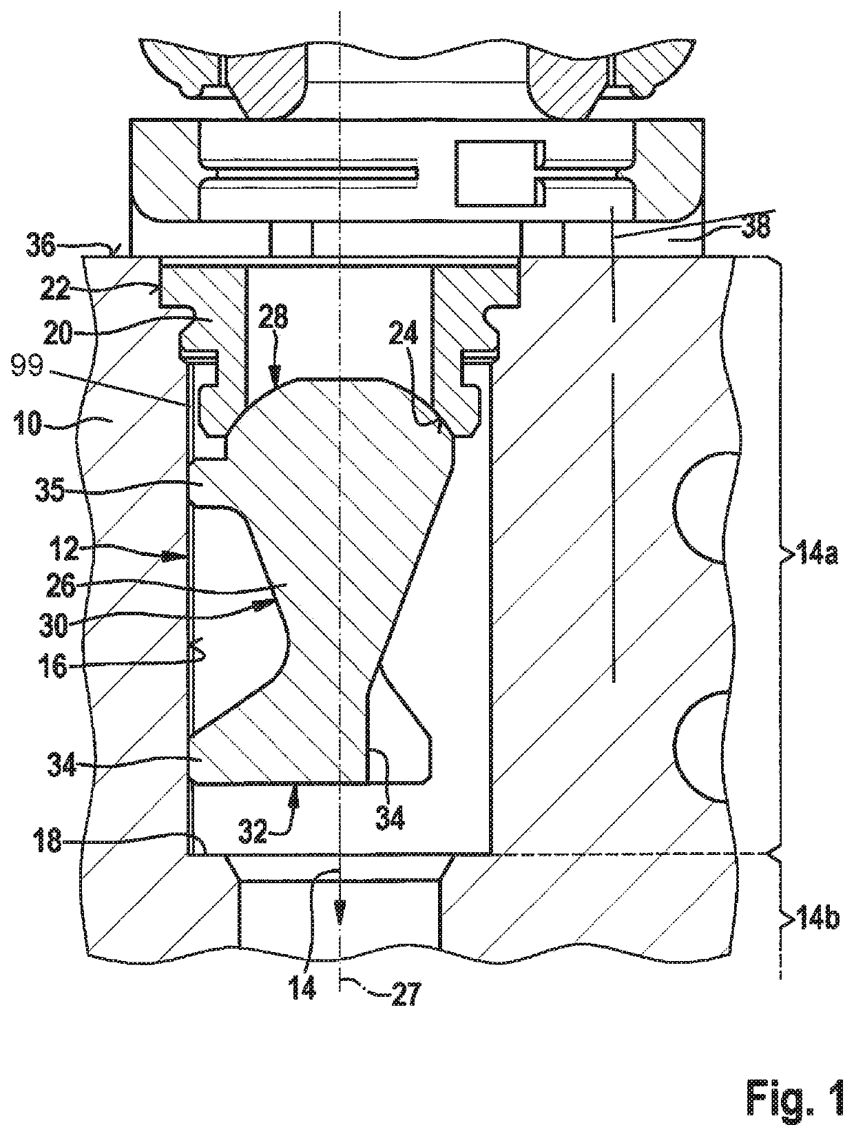
[0026]FIG. 1 shows a schematic partial view of a first specific embodiment of the hydraulic block.

[0027]Hydraulic block 10, which is partially shown schematically in FIG. 1, is formed from at least one metal (for example, aluminum) and / or at least one plastic. Hydraulic block 10 is preferably a cast part or an injection-molded part, or an extrusion with subsequent mechanical machining. It is to be noted that an ability to form hydraulic block 10 is not restricted to the use of a specific material for this purpose.

[0028]Hydraulic block 10 includes at least one check valve 12, which is situated in a check valve receiving bore 14 extending partially through hydraulic block 10. Check valve receiving bore 14 is formed as a stepped recess in hydraulic block 10. The forming of check valve receiving bore 14 in hydraulic block 10 is to be understood to mean that check valve receiving bore 14 is not an opening of an insert part inserted into hydraulic block 10. Instead, at least one inner wal...


PUM


Abstract

A hydraulic block is described for a braking system of a vehicle including at least one check valve, which is situated in a check valve receiving bore extending partially through the hydraulic block, including a valve seat and a valve body, the check valve receiving bore being formed as a stepped recess into the hydraulic block including a first subarea having at least one minimum diameter and an inner second subarea having at most one maximum diameter smaller than the minimum diameter; the valve seat is inserted onto and / or into the check valve receiving bore in a direct contact with at least one inner wall of the check valve receiving bore; and the valve body being inserted cageless and adjustable within the first subarea of the check valve receiving bore. A braking system for a vehicle and a manufacturing method for a hydraulic block for a braking system of a vehicle including at least one check valve are also described.

Description

FIELD OF THE INVENTION[0001]The present invention relates to a hydraulic block for a braking system of a vehicle and a braking system for a vehicle. The present invention also relates to a manufacturing method for a hydraulic block for a braking system of a motor vehicle having at least one check valve.BACKGROUND INFORMATION[0002]A braking system for a vehicle, which is equipped with a motorized piston-cylinder device for autonomous brake pressure buildup, is described in German Published Patent Application No. 10 2014 215 311. During the autonomous brake pressure buildup, a standard pedal feeling is able to be ensured for a driver actuating a brake pedal of the braking system with the aid of at least one simulator device. Both the at least one simulator device of the braking system and the motorized piston-cylinder device are each connected via a check valve to a brake fluid reservoir of the braking system.SUMMARY[0003]The present invention provides a hydraulic block for a braking ...

Claims


Application Information

Patent Timeline
Patent Type & Authority Patents(United States)
IPC IPC(8): B60T8/34B60T8/36B60T8/40B60T7/04
CPCB60T8/368B60T8/341B60T8/4081B60T7/042B60Y2400/81
Inventor WEH, ANDREASGUGGENMOS, HARALD
Owner ROBERT BOSCH GMBH
Why Eureka
Try Eureka