
Acoustic window layer for an ultrasound array

a technology of ultrasound array and acoustic window layer, which is applied in the field of acoustic window layer for ultrasound array, can solve the problems of image artifacts, inability to provide acoustic window material, and high cost of ultrasound ultrasound applications, so as to improve the propagation of acoustic waves

Active Publication Date: 2020-08-11
KONINKLJIJKE PHILIPS NV
View PDF8 Cites 0 Cited by
  • Summary
  • Abstract
  • Description
  • Claims
  • Application Information

AI Technical Summary

Benefits of technology

The present invention provides an acoustic window layer for an ultrasound array that combines improved acoustic wave propagation with chemical and mechanical stability. The layer is made by blending a thermoplastic polyolefin polymer with a polyolefin elastomer. This blend has low acoustic wave attenuation and is resistant to disinfectants. It also provides good mechanical protective properties and is bio compatible. The resulting blend has an increased shear wave attenuation that reduces cross talk between transducer elements. The acoustic window layer has a relatively low density and shows acoustic wave velocity in between 2000 and 1900 mm / msec, which improves image quality. The use of a thermoset rubber in the layer may improve acoustic contact and provide an improved transition of the acoustic wave throughout the layer.

Problems solved by technology

However, polymethylpentene based polymers used as a part of acoustic windows and lenses in the ultrasound imaging systems introduce image artifacts.
Furthermore, polymethylpentene based polymers have an acoustic impedance of 1.7 MRayls or higher, which is too high for some of the medical ultrasound applications.
Currently there is no available as acoustic windows material, which would meet most of the ultrasound system's requirements.

Method used


Image

  • Acoustic window layer for an ultrasound array
  • Acoustic window layer for an ultrasound array
  • Acoustic window layer for an ultrasound array

Examples


Embodiment Construction

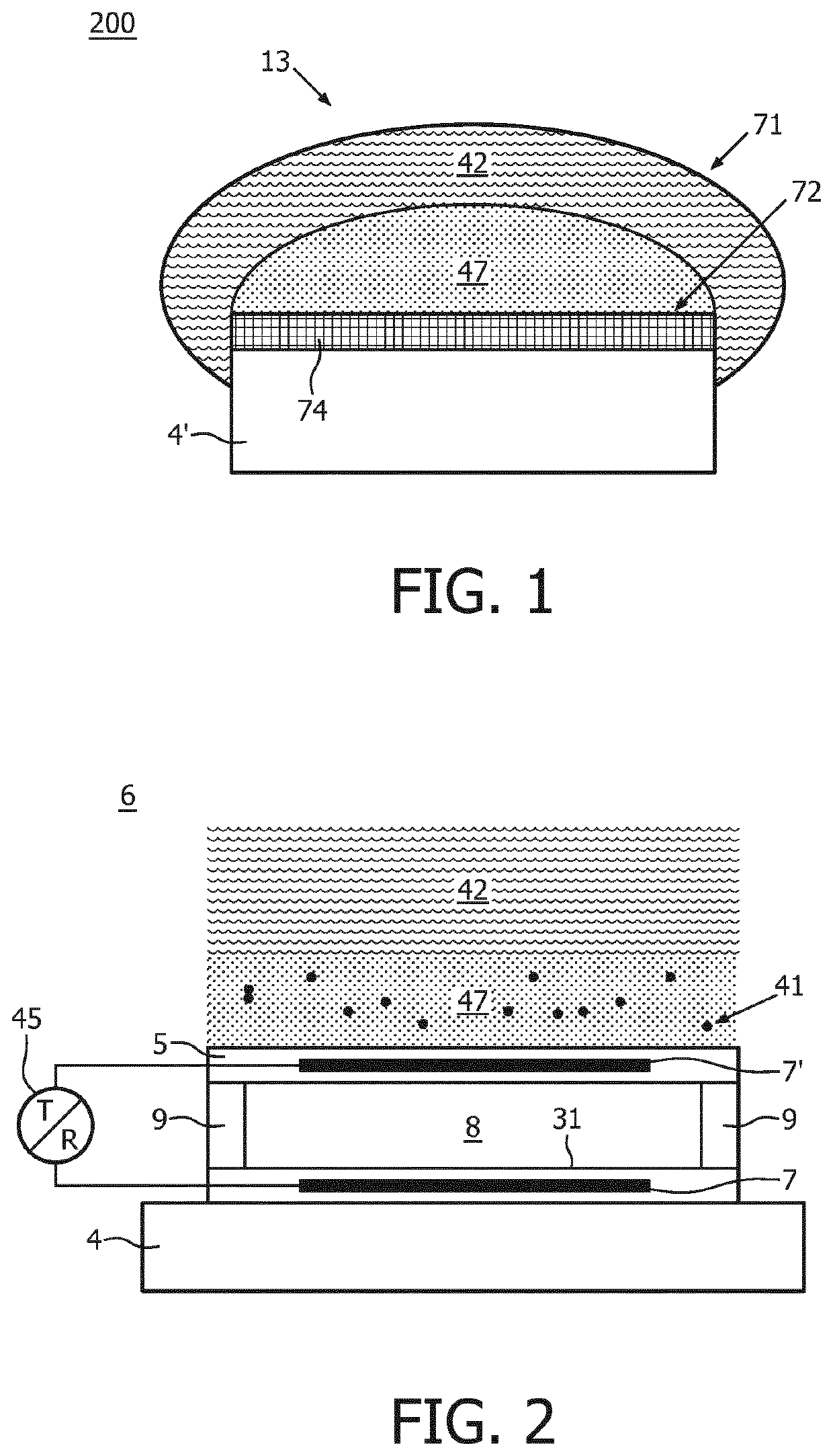
[0031]FIG. 1 shows schematically and exemplarily an embodiment of an ultrasound probe 200 according to the invention, comprising an ultrasound array 74. The ultrasound array 74 has an ultrasound wave emitting side facing an inner surface 72 of an acoustic window layer 13 and a backing side opposite to the emitting side. The ultrasound array may contain ultrasound transducers coupled to an integrated circuitry adapted to drive and control the transducers in the array. The backing side of the array is electrically coupled to a probe's base 4′, which communicates input and output signals of the integrated circuitry to and from an ultrasound system 202 (FIG. 8).

[0032]The acoustic window layer 13 comprises an outer layer 42 located at an outer surface of the acoustic window layer 13. The outer surface is intended to face a patient 201 or a body to be examined by the ultrasound imaging system 202. The outer layer 42 comprises a blend of a thermoplastic polymer selected from a polyolefin f...


PUM

PropertyMeasurementUnit
acoustic wave velocityaaaaaaaaaa
densityaaaaaaaaaa

Abstract

An acoustic window layer for an ultrasound array, which layer has an inner surface arranged to face the array and an outer surface arranged to face a patient, and comprising an outer layer comprising a thermoplastic polymer selected from a polyolefin family (TPO) and an elastomer selected from the polyolefin family (POE) blended therein, wherein the outer layer located at the outer surface of the acoustic window layer. In a preferred embodiment the blend comprises a copolymer of ethylene-octene and polymethylpentene. The thermoplastic polyolefin provides the blend with mechanical, chemical stability and low acoustic wave attenuation; whilst the polyolefin elastomer provides a possibility to tune the acoustic impedance of the blend and to further improve its acoustic wave propagation properties.

Description

[0001]This application is the U.S. National Phase application under 35 U.S.C. § 371 of International Application No. PCT / EP2016 / 077244, filed on Nov. 10, 2016, which claims the benefit of Provisional Application Ser. No. 62 / 253,484 filed Nov. 10, 2015 and EP Application Serial No. 16151635.6, filed Jan. 18, 2016. These applications are hereby incorporated by reference herein.FIELD OF THE INVENTION[0002]The invention relates to an acoustic window layer for an ultrasound array having an inner surface arranged to face the array and an outer surface arranged to face a patient.[0003]The invention further relates an ultrasound probe comprising such an acoustic window layer.BACKGROUND OF THE INVENTION[0004]Ultrasound transmitting components, such as acoustic windows and lenses, for medical imaging systems are desired to comply with several requirements, such as providing: an optimal low loss acoustic wave transmission; chemical and mechanical barriers to protect the ultrasound array elemen...

Claims


Application Information

Patent Timeline
Patent Type & Authority Patents(United States)
IPC IPC(8): A61B8/00G01S15/89B06B1/02G01S7/52A61L31/04G10K11/00
CPCA61B8/4483G01S7/52079G10K11/002G01S15/8938B06B1/0207B06B1/0292A61L31/049A61L31/048
Inventor MICHALSKI, PAWELHAKKENS, FRANCISCUS JOHANNES GERARDUSBERBEN, EDWARD THEODORUS MARIAWICKLINE, KEVIN GRAYSONBECKERS, LUCAS JOHANNES ANNA MARIADIRKSEN, PETER
Owner KONINKLJIJKE PHILIPS NV
Learn More