Lighting device

a technology of light source and light tube, which is applied in the direction of lighting support devices, lighting and heating apparatus, instruments, etc., can solve the problems of limited degree of design freedom in the desired shape, mechanical complexity of device configuration, and difficult installation or manipulation, so as to achieve flexibility of light passage portion, enhance design freedom, and high versatility

Active Publication Date: 2020-08-18
LG INNOTEK CO LTD
View PDF16 Cites 0 Cited by
  • Summary
  • Abstract
  • Description
  • Claims
  • Application Information

AI Technical Summary

Benefits of technology

[0010]According to an embodiment of the present invention, a light image having a stereoscopic effect can be implemented using light emitted from a light-emitting device and simultaneously, a structure of a printed circuit board (PCB) located at a lower portion of a light passage portion is eliminated and a direct-type light-emitting device located at sides of the light passage portion and having high versatility is used such that flexibility of the light passage portion is attained and a degree of freedom of design can be enhanced.
[0011]Also, a lighting device in which a stereoscopic effect is implemented and which simultaneously has a flexible structure on a sheet and can be effectively used in a flat surface or an inside / outside curved portion of an object in which lighting is required to be installed, such as a building, a facility, a furniture, or a car, can be provided.
[0012]Furthermore, according to an embodiment of the present invention, a reflection member and a transparent support member are located at the lower portion of the light passage portion so that a lighting device can be designed in such a way that the lighting device includes various designs which may be exposed when the lighting device is turned on according to a design of the reflection member.
[0013]In addition, an arrangement structure of an existing printed circuit board (PCB) is eliminated from the lower portion of the light passage portion so that the entire thickness of the lighting device is reduced. When a light-emitting diode (LED) package, such as a chip scale package (CSP), is used, the thickness of a lead frame or wire is eliminated so that the light device can be made to be thinner and thus, the lighting device that realizes a three-dimensional (3D) image with a thinner structure can be implemented.
[0014]Furthermore, a light image of a linear light which has various shapes of stereoscopic effects can be implemented according to relative positions of light sources and patterns or a slope or curvature of the patterns themselves. The lighting device that can be easily used in an inside / outside curved portion of an object in which lighting is required to be installed, such as a building, a facility, a furniture, or a car, using a structure of the flexible sheet can be provided. Also a lighting device for a vehicle which is provided on the flexible sheet that is advantageous in various aspects such as volume, thickness, weight, price, life span, stability, a degree of freedom of design, and installation feasibility can be provided as a lamp (a headlight, a rear light, a fog light, an indoor light, a door scarf) for the vehicle.

Problems solved by technology

However, when the atmosphere is expressed in a desired shape or color using a lighting device according to the related art, the configuration of a device is mechanically complicated.
Thus, a degree of freedom of design in the desired shape is limited, and installation or manipulation is difficult.
However, due to a structural limitation of a light-emitting package itself, it is difficult to freely make a design and to satisfy implementation of aesthetic elements of an image when the lighting device is not turned on.

Method used


Image

  • Lighting device
  • Lighting device
  • Lighting device

Examples


Embodiment Construction

[0024]Hereinafter, a configuration and an operation of the present invention will be described in detail with reference to the accompanying drawings. Like reference numerals represent the same components regardless of the number of the drawings, and a detailed description thereof will be omitted. It will be understood that, although the terms first, second, etc. may be used herein to describe various elements, these elements should not be limited by these terms. These terms are only used to distinguish one element from another.

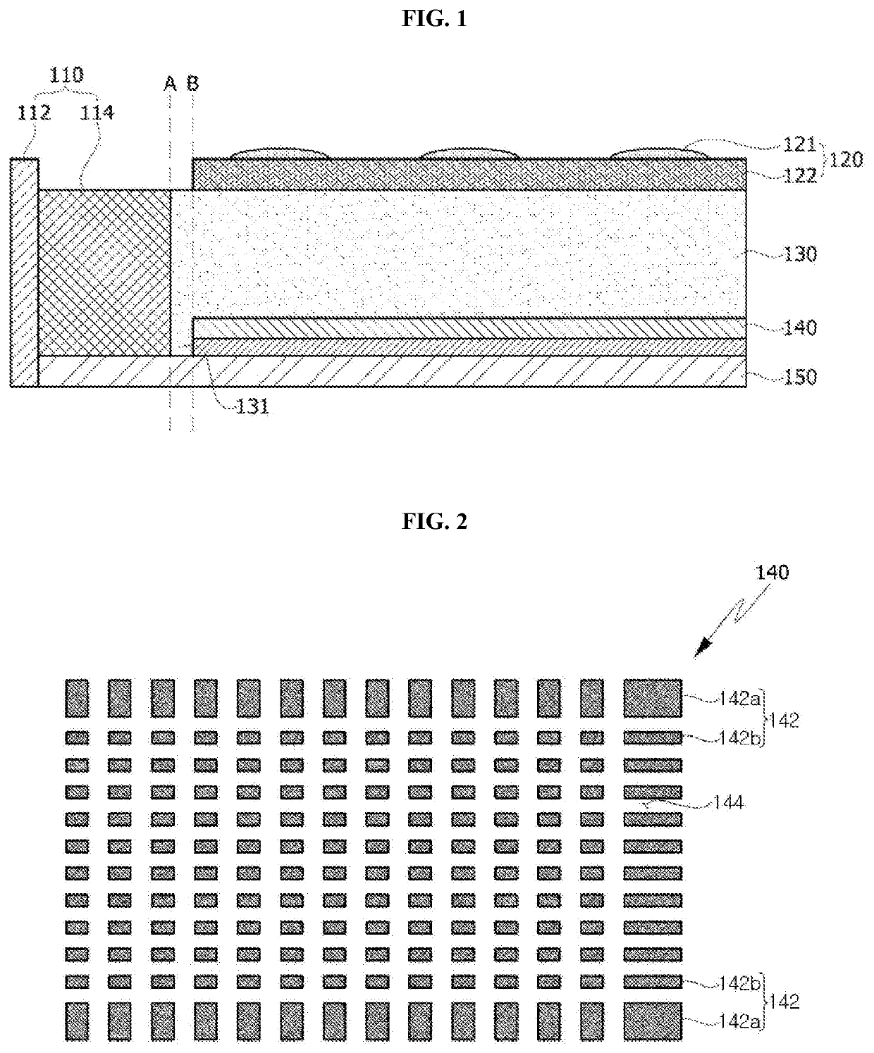
[0025]FIG. 1 is a cross-sectional conceptual view of essential portions of a lighting device according to an embodiment of the present invention (hereinafter, referred to as a ‘present device’).

[0026]Referring to FIG. 1, the present device may include a light guide unit 130 that induces light and emits the guided light to a light exiting surface, a light source unit 110 located at sides of the light guide unit 130 and emitting light inside the light guide unit...


PUM

PropertyMeasurementUnit
surface roughnessaaaaaaaaaa
inclination angleaaaaaaaaaa

Abstract

Provided is a lighting device that converts an exiting light into a stereoscopic light having a sense of depth or a sense of volume, whereby light images having stereoscopic effects can be implemented using light emitted from a light-emitting device and simultaneously, a structure of a printed circuit board (PCB) located at a lower portion of a light passage portion is eliminated and a direct-type light-emitting device located at sides of the light passage portion and having high versatility is used such that flexibility of the light passage portion is attained and a degree of freedom of a design can be enhanced.

Description

CROSS-REFERENCE TO RELATED PATENT APPLICATIONS[0001]This application is a U.S. National Stage Application under 35 U.S.C. § 371 of PCT Application No. PCT / KR2016 / 015013, filed Dec. 21, 2016, which claims priority to Korean Patent Application No. 10-2015-0183017, filed Dec. 21, 2015, whose entire disclosures are hereby incorporated by reference.TECHNICAL FIELD[0002]The present invention relates to a lighting device that converts an exiting light into a stereoscopic light having a sense of depth and a sense of volume.BACKGROUND ART[0003]In general, lighting devices are devices that make a dark portion bright using a variety of light sources. Lighting devices are used to illuminate a certain object or place and to express an atmosphere with a desired shape or color.[0004]Recently, a variety of lighting devices using a light-emitting diode (LED) have become popular due to development of an LED technology. For example, a lighting device according to the related art includes an LED light ...

Claims


Application Information

Patent Timeline
Patent Type & Authority Patents(United States)
IPC IPC(8): F21V21/00F21V33/00F21S43/14F21V7/10F21V7/04G02B30/27G02B6/00F21S43/239F21S43/31F21S43/245F21S43/20F21K9/61F21V19/00F21W107/10F21Y105/10F21Y115/00F21Y115/10G02B30/30
CPCF21S43/239F21V7/04F21S43/31F21S43/14F21V7/10F21K9/61F21S43/26F21V33/006F21V19/001G02B6/00G02B30/27F21S43/245F21Y2115/00F21Y2115/10F21Y2105/10G02B6/0083G02B6/0038G02B6/002F21S41/24F21S41/37F21S43/195F21S43/33F21S41/192F21S41/141G02B30/30
Inventor LIM, EAY JINJANG, JAE HYUKYANG, HYUN DUCK
Owner LG INNOTEK CO LTD
Why Eureka
Try Eureka