Light detector, correction coefficient calculation device, and correction coefficient calculation method

a correction coefficient and calculation method technology, applied in the field of light detectors, can solve the problems of deteriorating the detection accuracy of light detectors, significant increase in cost, and limited dynamic range of light detectors, and achieve the effect of wide dynamic range and high accuracy

Active Publication Date: 2020-09-01
SEIKO EPSON CORP
View PDF3 Cites 0 Cited by
  • Summary
  • Abstract
  • Description
  • Claims
  • Application Information

AI Technical Summary

Benefits of technology

[0008]An advantage of some aspects of the invention is to provide a light detector having a wide dynamic range and high accuracy even when a general-purpose operational amplifier is used for a variable amplification circuit, and a correction coefficient calculation device and a correction coefficient calculation method for correcting the dark voltage value in the light detector.
[0010]In the aspect of the invention, a dark voltage value corresponding to the gain set in the variable amplification circuit can be corrected by using a correction coefficient calculated by a dark voltage correction unit. For example, the corrected dark voltage value is calculated by multiplying the gain set in the variable amplification circuit by the correction coefficient. By using such a corrected dark voltage value, even when the gain for variable amplification circuit is set as a low value, correction of subtracting the dark voltage value from the output value of the variable amplification circuit can be performed accurately. Therefore, it is unnecessary to limit the range of the gains set in the variable amplification circuit, and the wide dynamic range of the light detector can be set.
[0013]Further, according to the aspect of the invention, since a general-purpose operational amplifier can be used to construct the variable amplification circuit, the cost can be reduced as compared with the case of using a rail-to-rail operational amplifier.
[0017]In the aspect of the invention, the output value correction unit can accurately correct the output value of the variable amplification circuit by using the correction coefficient or the dark voltage table stored in the storage unit. As a result, even when a general-purpose operational amplifier is used for a variable amplification circuit, a light detector with a wide dynamic range and high accuracy can be provided.
[0023]In the aspect of the invention, the dark voltage value of the light receiver with respect to the gain of the variable amplification circuit can be corrected by using the correction coefficient calculated by the dark voltage correction unit. For example, the corrected dark voltage value is calculated by multiplying the gain of the variable amplification circuit by the correction coefficient. By using such a corrected dark voltage value, even when the gain for variable amplification circuit is set as a low value, correction of subtracting the dark voltage value from the output value of the light receiver can be performed accurately. Therefore, it is unnecessary to limit the range of the gains set in the variable amplification circuit, and a wide dynamic range of the light detector can be set.

Problems solved by technology

The collapse phenomenon of the dark voltage as described above becomes an error during correcting in which a dark voltage value is subtracted from an output value of the variable amplification circuit, thus deteriorating the detection accuracy of the light detector.
In order to avoid the error, it is necessary to limit the range of the gains set in the variable amplification circuit, but in this case, dynamic range of the light detector is limited.
In addition, the problem described above is a problem that occurs when a general-purpose operational amplifier capable of handling signals only in a limited range of power supply voltage is used as an operational amplifier constituting the variable amplification circuit.
When a rail-to-rail operational amplifier capable of handling signals over entire range of the power supply voltage is used, this problem can be solved, but in this case, the cost is significantly increased.

Method used


Image

  • Light detector, correction coefficient calculation device, and correction coefficient calculation method
  • Light detector, correction coefficient calculation device, and correction coefficient calculation method
  • Light detector, correction coefficient calculation device, and correction coefficient calculation method

Examples


first embodiment

[0032]A first embodiment of the invention will be described with reference to the drawings. In the present embodiment, a spectroscopic measurement device which is an example of a light detector according to the invention will be described.

Configuration of Spectroscopic Measurement Device

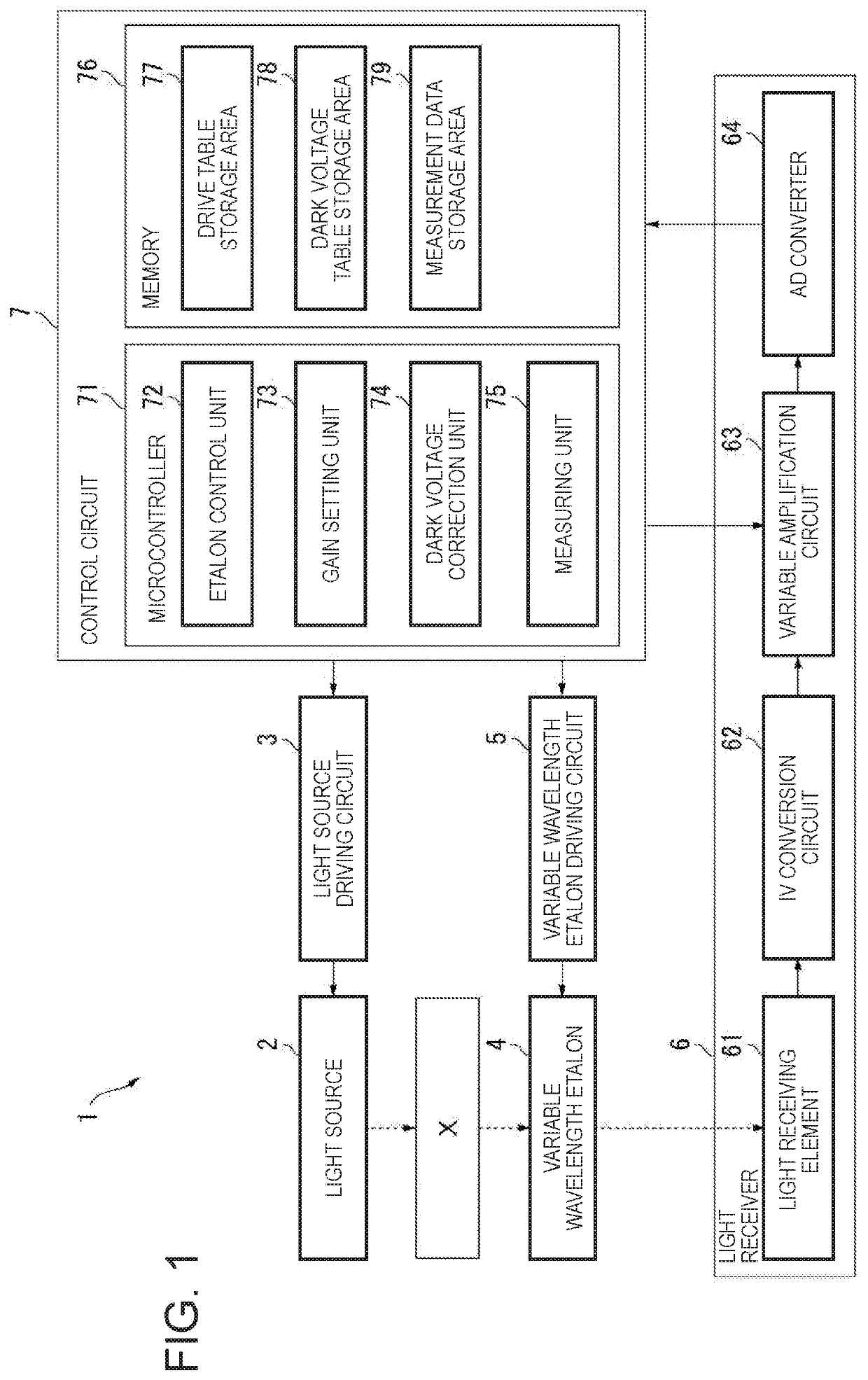
[0033]As shown in FIG. 1, a spectroscopic measurement device 1 is an apparatus that measures an amount of light of each wavelength in a measurement target light reflected by a measurement target object X, and includes a light source 2, a light source driving circuit 3, a variable wavelength etalon 4, a variable wavelength etalon driving circuit 5, a light receiver 6, and a control circuit 7.

[0034]The light source 2 has elements that convert electric signals of a plurality of LEDs or semiconductor lasers having different peak emission wavelengths into light, and is turned on, turned off, and dimmed by the light source driving circuit 3 controlled by a control circuit 7.

[0035]The variable wavelength et...

second embodiment

[0075]A spectroscopic measurement device 1A according to a second embodiment of the invention will be described with reference to FIG. 6. The same reference numerals are given to the same components as those of the first embodiment, and the explanation thereof will be simplified or not be repeated.

[0076]In the first embodiment, while the dark voltage correction unit 74 calculates the correction coefficient a and generates the dark voltage table, the spectroscopic measurement device 1A according to the second embodiment does not include such a dark voltage correction unit 74. That is, in the second embodiment, at the time of manufacturing the spectroscopic measurement device 1A, at least one of the correction coefficient a or the dark voltage table is stored in the dark voltage table storage area 78.

[0077]For example, when the dark voltage table is stored in the dark voltage table storage area 78, the measuring unit 75 can correct the output value of the light receiver 6 using the co...

third embodiment

[0079]Like the second embodiment, a correction coefficient calculation device 8 according to the third embodiment of the invention will be described with reference to FIG. 6. The same reference numerals are given to the same components as those of the first embodiment, and the explanation thereof will be simplified or not be repeated.

[0080]The correction coefficient calculation device 8 according to the embodiment includes an arithmetic operation unit 84 having the same function as that of the dark voltage correction unit 74 of the first embodiment. This correction coefficient calculation device 8 is connected to the spectroscopic measurement device 1A according to the second embodiment, for manufacturing the spectroscopic measurement device 1A. Then, the arithmetic operation unit 84 stores at least one of the correction coefficient a or the dark voltage table in the dark voltage table storage area 78 of the spectroscopic measurement device 1A by performing the dark voltage correcti...


PUM


Abstract

A spectroscopic measurement device includes a light receiving element that receives light and outputs a light receiving signal, a variable amplification circuit that amplifies the light receiving signal which is input, and a dark voltage correction unit that calculates a correction coefficient that is a rate of change of a dark voltage value with respect to gains, based on an output value of the variable amplification circuit with each value of two or more gains which are equal to or greater than a predetermined value in an environment where no light is incident on the light receiving element.

Description

BACKGROUND1. Technical Field[0001]The present invention relates to a light detector, a correction coefficient calculation device, and a correction coefficient calculation method.2. Related Art[0002]In the related art, there is a light detector that irradiates a workpiece with measurement light and detects light reflected by the workpiece with a light receiving element to perform various processes such as measurement and capturing of the workpiece (see, for example, JP-A-2012-247286). In such a light detector, a current signal outputted from a light receiving element according to an amount of received light is converted into a voltage signal by an IV conversion circuit, and the voltage signal is amplified by an amplification circuit and then converted into a digital signal by an AD converter.[0003]In a spectroscopic measurement device disclosed in JP-A-2012-247286, a variable amplification circuit having gain switching function is used as the amplification circuit described above. Th...

Claims


Application Information

Patent Timeline
Patent Type & Authority Patents(United States)
IPC IPC(8): G01J1/44G01J3/28G01J3/26
CPCG01J3/26G01J3/28G01J3/2803G01J1/44G01J2001/444G01J1/42
Inventor KURI, RYOHEI
Owner SEIKO EPSON CORP
Why Eureka
Try Eureka