Inductor winding method and inductor winding device

a winding method and inductor technology, applied in the field of inductor winding methods, can solve the problems and achieve the effect of increasing inductor loss and disadvantageous efficiency optimization

Active Publication Date: 2020-09-01
EMERSON NETWORK POWER CO LTD
View PDF25 Cites 0 Cited by
  • Summary
  • Abstract
  • Description
  • Claims
  • Application Information

AI Technical Summary

Benefits of technology

[0028]The winding method and winding device for inductor disclosed in the above have the following advantages. With a coupling inductor having an interleaving-wound structure, power frequency magnetic fluxes generated by magnetic lines in magnetic columns counteract one another, thereby solving the problem of high magnetic flux density in a magnetic core while achieving certain leakage inductance. In addition, coupling coefficients between the windings of the coupling inductor are increased and power frequency magnetic flux density is reduced.

Problems solved by technology

The present disclosure provides an inductor winding method and an inductor winding device, to address a technical problem in the conventional technology that, magnetic fluxes generated by power frequency currents in three windings cannot counteract one another completely, thereby causing the saturation of the magnetic core, increasing the inductor loss, which is disadvantageous for efficiency optimization.

Method used


Image

  • Inductor winding method and inductor winding device
  • Inductor winding method and inductor winding device
  • Inductor winding method and inductor winding device

Examples


first embodiment

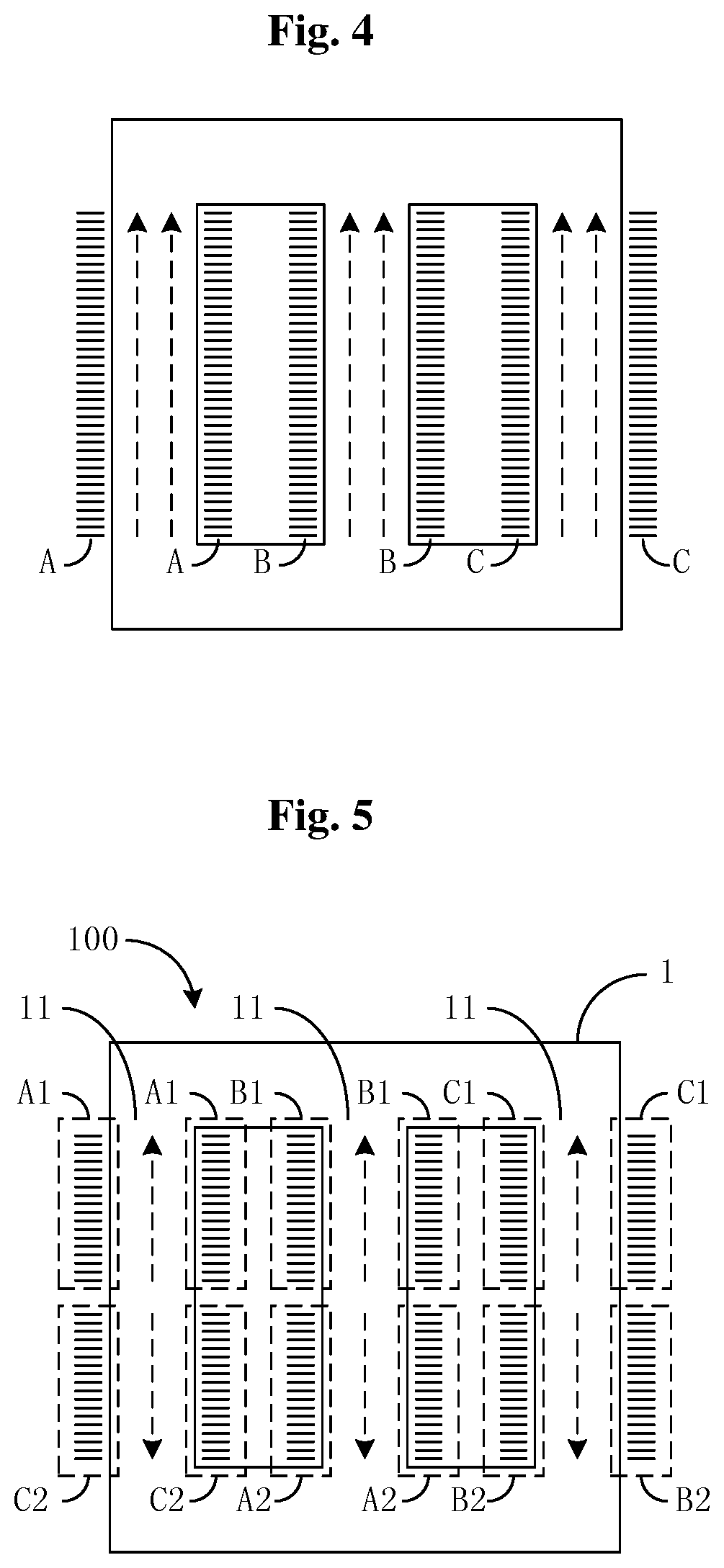
[0079]FIG. 10a is a schematic wiring diagram of an interleaving-wound structure for the inductor 2 according to the present disclosure. The winding A1 and the winding C2 are wound on the same magnetic column 11. If the winding A1 is wound clockwise from top to bottom, the winding C2 is wound anticlockwise from top to bottom. The winding B1 and the winding A2, and the winding C1 and the winding B2 are also wound in the same manner.

second embodiment

[0080]FIG. 10b is a schematic wiring diagram of an interleaving-wound structure for the inductor 2 according to the present disclosure. The winding A1 and the winding B2 are wound on the same magnetic column 11. If the winding A1 is wound clockwise from top to bottom, the winding B2 is wound anticlockwise from top to bottom. The winding B1 and the winding C2, and the winding C1 and the winding A2 are also wound in the same manner.

third embodiment

[0081]FIG. 10c is a schematic wiring diagram of an interleaving-wound structure for the inductor 2 according to the present disclosure. The winding A1 and the winding C2 are wound on the same magnetic column 11. If the winding A1 is wound clockwise from top to bottom, the winding C2 is wound clockwise from bottom to top. The winding B1 and the winding A2, and the winding C1 and the winding B2 are also wound in the same manner.


PUM

PropertyMeasurementUnit
magnetic flux densityaaaaaaaaaa
diameteraaaaaaaaaa

Abstract

Provided is an inductor winding method and an inductor winding device. The inductor winding method comprises steps of: A. dividing turns of coil of each winding of the inductor into a first winding and a second winding based on a preset ratio; B. winding the first winding on one of multiple magnetic columns, and winding the second winding on another one of the multiple magnetic columns which is different from the magnetic column on which the first winding is wound; and C. performing step A and step B cyclically until all the windings of the inductor are wound. With a coupling inductor having interleaving-wound structure, power frequency magnetic fluxes generated by magnetic lines in magnetic columns counteract one another, thereby solving the problem of high magnetic flux density in a magnetic core while achieving certain leakage inductance.

Description

CROSS-REFERENCE TO RELATED APPLICATIONS[0001]This application claims the benefit and priority of Chinese Application No. 2016101 09545.5, filed on Feb. 26, 2016, the entire disclosure of which is incorporated herein by reference.TECHNICAL FIELD[0002]The present disclosure generally relates to the technical field of inductor, and in particular to an inductor winding method and an inductor winding device.BACKGROUND[0003]An interleaved parallel connected power converter can improve efficiency and power density while cancel current ripple and improve input or output characteristics. Therefore, the interleaved parallel connected power converter is widely applied in power factor correction circuits, inverter circuits and direct-current (DC) converting circuits. A typical two-phase interleaved circuit is shown in FIG. 1, where each phase of the circuit includes a separate filter inductor, denoted as L1 and L2 respectively. A dedicated control loop needs to be designed in the interleaved pa...

Claims


Application Information

Patent Timeline
Patent Type & Authority Patents(United States)
IPC IPC(8): H01F41/06H01F41/069H01F27/38H01F37/00H01F38/08H01F27/30H02M1/00H02M1/14H02M3/158H01F38/02
CPCH01F37/00H01F38/08H01F41/069H01F27/38H02M2001/0064H01F27/306H01F2038/026H02M3/1584H02M1/14H01F27/24H01F41/06H02M1/0064
Inventor WEI, YUNFENGSHI, YAMINGXU, FUBIN
Owner EMERSON NETWORK POWER CO LTD
Why Eureka
Try Eureka