Eureka AIR delivers breakthrough ideas for toughest innovation challenges, trusted by R&D personnel around the world.

Composite articles with dielectric layer

a dielectric layer and composite material technology, applied in the field of composite articles, can solve the problems of difficult to make either thick or thin film piezoelectric devices of high sensitivity, difficult to find materials with comparable performance, and difficult to make piezoelectric devices with high sensitivity. , to achieve the effect of enhancing the piezoelectric response of piezoelectric materials

Active Publication Date: 2020-09-01
EASTMAN KODAK CO
View PDF11 Cites 0 Cited by
  • Summary
  • Abstract
  • Description
  • Claims
  • Application Information

AI Technical Summary

Benefits of technology

[0030]Approaches in the prior art to improve the performance of piezoelectric devices concentrate on collecting charge from the direction of the largest piezoelectric coefficient that is accessible given the geometry of a device (meaning the actual architecture of the device and how it is poled). This is exemplified in the use of interdigitated electrode architectures in many known piezoelectric devices. These specialized electrode architectures as currently practiced in the art do not affect the fundamental piezoelectric coefficients of the piezoelectric materials used in device construction. An advantage of the present invention, particularly the composite article structure, is the ability to directly manipulate and improve the piezoelectric charge coefficient d33 of a device without depending upon its structure. This is fundamentally different from articles of the prior art that have been reduced to practice by direct measurement of the fundamental piezoelectric charge coefficient d33 for different composite electrode structures.
[0031]Specifically, it has been discovered that an inventive composite article (or electrode) design including a dry piezoelectric layer (PL) and one or more layers or co-planar electrodes containing (b) particles (described below), and devices prepared from such composite articles can enhance the piezoelectric response of piezoelectric materials measured in terms of d33. In some embodiments, the inventive composite article design comprises one or more dry electrically-conductive layers (dry ECL-P's) containing a novel electrically-conductive EC-P composition comprising required (b) particles of certain characteristics and having a different Young's modulus different from the one or more (a) electrically-conductive materials that are used in the dry ECL-P (electrode) to collect the charge generated by the dry piezoelectric layer (dry PL).
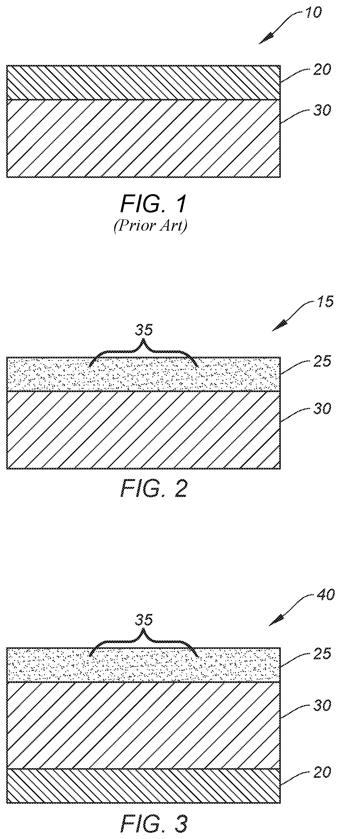
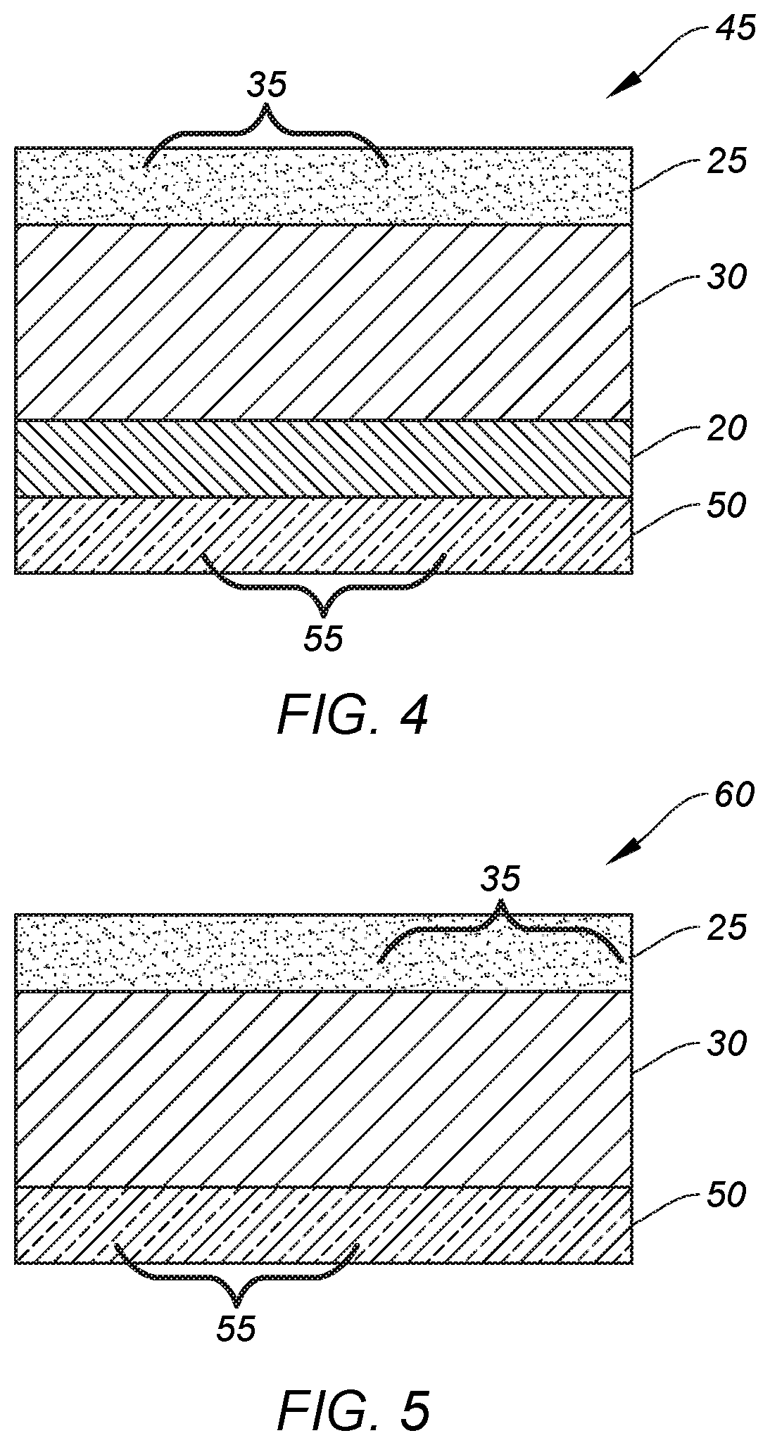
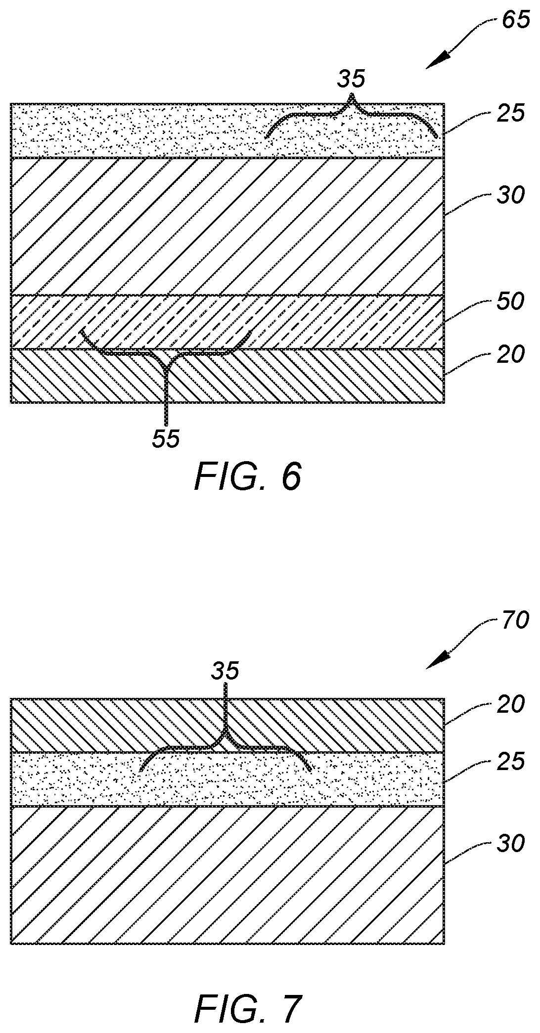
[0032]In other embodiments, a dry PL is used with at least one dry dielectric layer (dry DL-P) containing (b) particles as described below.
[0033]In many embodiments, the EC-P compositions are used to provide uniform layers, but in some embodiments, non-electrically-connected co-planar patterned electrodes can be prepared from an EC-P composition and such electrodes are not uniform layers and are not electrically connected to each other. Yet, these non-electrically-connected co-planar patterned electrodes also contain the (b) particles as defined below.
[0034]Details of the noted (b) particles are provided below. In some embodiments, the (b) particles are non-compressible but in other embodiments, they are elastic and compressible. Moreover, the (b) particles can be either insulating or electrically-conductive. In embodiments using silver nanoparticles as the electrically-conductive material, the d50 of the (b) particles is greater than the d50 of those silver nanoparticles.
[0035]Without being limited to a particular mechanism or theory, it is believed that the function of the (b) particles is to affect the distribution of stress within the dry piezoelectric layer (dry PL) upon application of force to a dry ECL-P or dry DL-P surface or to the surface of non-electrically-connected co-planar patterned electrodes containing (b) particles, thereby affecting the magnitude of the piezoelectric effect as measured as d33. It is believed that when the dry ECL-P, dry DL-P, or non-electrically-connected co-planar patterned electrode network is flexible and deformable during application of stress (force), the stress distribution propagated throughout that network to the dry PL is primarily determined by the nature of the (b) particles and their distribution within the dry ECL-P, dry DL-P, or non-electrically-connected co-planar patterned electrodes.

Problems solved by technology

A common piezoelectric material is lead zirconate titanate (PZT) but as one might suspect, such material raises both environmental and public health concerns relating to both production and use because of the presence of lead.
While lead zirconate titanate performs well, it has proven difficult in recent years to find materials with comparable performance so that PZT can be replaced.
It is also difficult to make either thick or thin film piezoelectric devices of high sensitivity, and thus, efforts are being undertaken to find improved materials without the presence of lead.
Thus, the transducer they proposed is mechanically unstable and impractical for any industrial use.
It is recognized by those skilled in the art of piezoelectric materials that piezoelectric polymers (such as PVDF), in general, have lower piezoelectric coefficients than crystalline inorganic piezoelectric materials such as PZT and that the lower piezoelectric coefficients of piezoelectric polymers have hampered the development of uses for these materials.

Method used


Image

  • Composite articles with dielectric layer
  • Composite articles with dielectric layer
  • Composite articles with dielectric layer

Examples


invention example 1

[0375]3 weight % of spherical crosslinked poly(styrene-co-divinyl benzene-co-ethylvinyl benzene) (b) particles (d50 particle size of 46 μm) was added to a weighed amount of the Comparative Example 1 EC composition described above before mixing using the FlackTek Speedmixer™ DAC 150 speedmixer.

invention example 2

[0376]7 weight % of spherical crosslinked poly(styrene-co-divinyl benzene-co-ethylvinyl benzene) (b) particles (d50 particle size of 91 μm) was added to a weighed amount of the Comparative Example 1 EC composition described above before mixing using the FlackTek Speedmixer™ DAC 150 speedmixer.

invention example 3

[0377]7 weight % of spherical crosslinked poly(styrene-co-divinyl benzene-co-ethylvinyl benzene) (b) particles (d50 particle size of 201 μm) was added to a weighed amount of the Comparative Example 1 EC composition described above before mixing using the FlackTek Speedmixer™ DAC 150 speedmixer.

[0378]The typical volume weighted frequency distribution for the particle size of crosslinked polystyrene particles used in Invention Examples 1-3 are shown in FIG. 21. The crosslinked polystyrene resin particles are comprised of beads of polystyrene resin (copolymer of styrene and divinylbenzene / ethylvinyl benzene mixture) as described in U.S. Pat. No. 7,441,717 (Majka et al.) and U.S. Pat. No. 5,478,705 (Caekai et al.) and are notated as Polybead® 50, Polybead® 100, and Polybead® 200 in the TABLE IV above. The preparation of such crosslinked polystyrene particles and other resin particles that are useful in the present invention is described in the noted U.S. Pat. No. 5,478,705 the disclosur...


PUM

PropertyMeasurementUnit
weight ratioaaaaaaaaaa
polydispersity coefficientaaaaaaaaaa
electrical conductivityaaaaaaaaaa

Abstract

A composite article useful in various electronic devices has 1) a dry piezoelectric layer (first dry PL) comprising a piezoelectric material, and 2) one or more dry dielectric layers arranged contiguously with opposing surfaces of the first dry PL. The dry dielectric layer has essentially: (a′) a dielectric material; and (b) particles having a Young's modulus that is different from the Young's modulus of the (a′) dielectric material by at least 10%. The (b) particles have a d50 of at least 500 nm and up to and including 500 m and a polydispersity coefficient that is less than or equal to 3, provided that the weight ratio of the (b) particles to the (a′) dielectric material is at least 0.01:1 and up to and including 10:1.

Description

RELATED APPLICATIONS[0001]Reference is made to the following commonly assigned and co-filed patent applications:[0002]U.S. Pat. No. 10,297,741, by Benedict and Sieber, and entitled “Electrically-conductive Compositions”;[0003]U.S. Pat. No. 10,305,022, by Benedict and Sieber, and entitled “Silver-containing Electrically-conductive Compositions”;[0004]U.S. Publication No. 2019 / 0189902, by Benedict and Sieber, and entitled “Piezoelectric Composite Articles”;[0005]U.S. Publication No. 2019 / 0189889, by Benedict, Sieber, and Tucker, and entitled “Piezoelectric Article with Dielectric Layer and Co-Planar Electrodes”;[0006]U.S. Publication No. 2019 / 0189892, by Benedict, Sieber, and Tucker, and entitled “Composite Article with Co-Planar Electrodes”;[0007]U.S. Publication No. 2019 / 0189893, by Sieber and Benedict, and entitled “Piezoelectric Capacitor”;[0008]U.S. Publication No. 2019 / 0189890, by Sieber and Benedict, and entitled “Piezoelectric Capacitor with Co-Planar Patterned Electrodes”;[00...

Claims


Application Information

Patent Timeline
Patent Type & Authority Patents(United States)
IPC IPC(8): H01L41/18H01L41/113H01L41/193H01L41/047H01L41/083H02N2/18H01L41/187H01L41/053
CPCH01L41/1138H01L41/183H01L41/0475H01L41/0478H01L41/0477H02N2/188H01L41/1132H02N2/181H01L41/193H01L41/083H01L41/187H01L41/053H01L41/1136H10N30/878H10N30/308H10N30/302H10N30/852H10N30/50H10N30/857H10N30/875H10N30/877H10N30/88H10N30/306H10N30/853
Inventor BENEDICT, ROBERTA DILEOSIEBER, KURT D.
Owner EASTMAN KODAK CO
Why Eureka
Eureka Blog
Learn More