Ear canal plug for detecting bio-electrical signals

a bioelectrical signal and ear canal technology, applied in the field of ear canal plugs for detecting bioelectrical signals, can solve the problem of difficult to obtain ear plugs with eeg electrodes, and achieve the effect of reliable and fas

Active Publication Date: 2020-09-08
T&W ENG
View PDF25 Cites 2 Cited by
  • Summary
  • Abstract
  • Description
  • Claims
  • Application Information

AI Technical Summary

Benefits of technology

[0012]In an embodiment of the ear plug the housing is compressible and the electrodes are arranged to follow a movement caused by a compression of the outer wall. This has the advantage that the whole ear plug is compressible as such, and not just the resilient outer wall. Thereby, the risk that the ear plug becomes irritating or annoying to wear over an extended period of time, such as several month or years, becomes significantly reduced.
[0013]In a further embodiment of the ear plug the outer wall of the housing is provided with a shape customized to the ear canal of an intended user. This will also make the ear plug more pleasant to wear and reduce the risk of annoyance or irritation.
[0014]In a further embodiment of the ear plug the skin contact part of the electrodes is provided with a layer of iridium oxide on at least the surface intended to touch the skin surface in ear, e.g. the ear canal or concha part of the ear. This has the advantage that a low impedance between skin and electrode can be achieved, and that the risk of skin irritation is reduced. One advantage of iridium oxide is that a relatively small geometric area of an electrode can be applied, and still achieving a large electrochemically effective area. When the layer of iridium oxide also comprises tantalum, these advantages are more profound. Concerning the low impedance, this is also the case when the layer of iridium oxide is porous.
[0015]In a further embodiment of the ear plug each one of the at least two electrodes are provided with an amplifying circuit, the amplifying circuit being shielded against electromagnetic noise. Thereby the electrodes are made into so called active electrodes, where the signal delivered from the electrode is more powerful and therefore less sensitive to noise. The amplifying circuit may also have an analogue to digital (A / D) converter, making the signal from the electrode even less sensitive to noise.

Problems solved by technology

One problem with the known solutions is that it is difficult to obtain an ear plug with EEG electrodes which is both pleasant and not annoying to wear for extended periods of time, and at the same time can obtain a stable and reliable EEG signal.

Method used


Image

  • Ear canal plug for detecting bio-electrical signals
  • Ear canal plug for detecting bio-electrical signals
  • Ear canal plug for detecting bio-electrical signals

Examples


Embodiment Construction

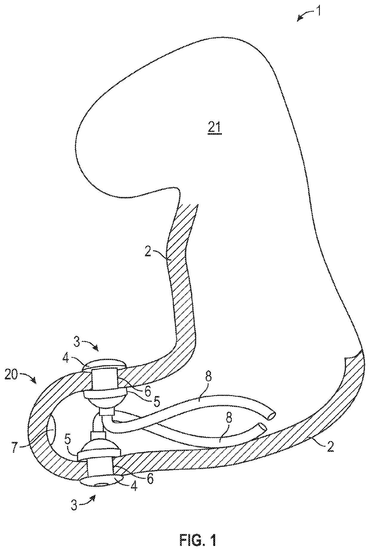
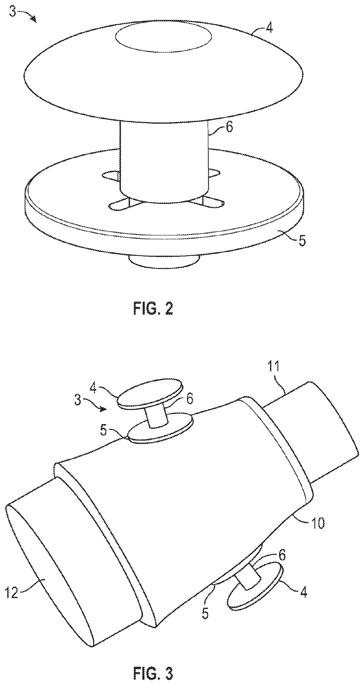
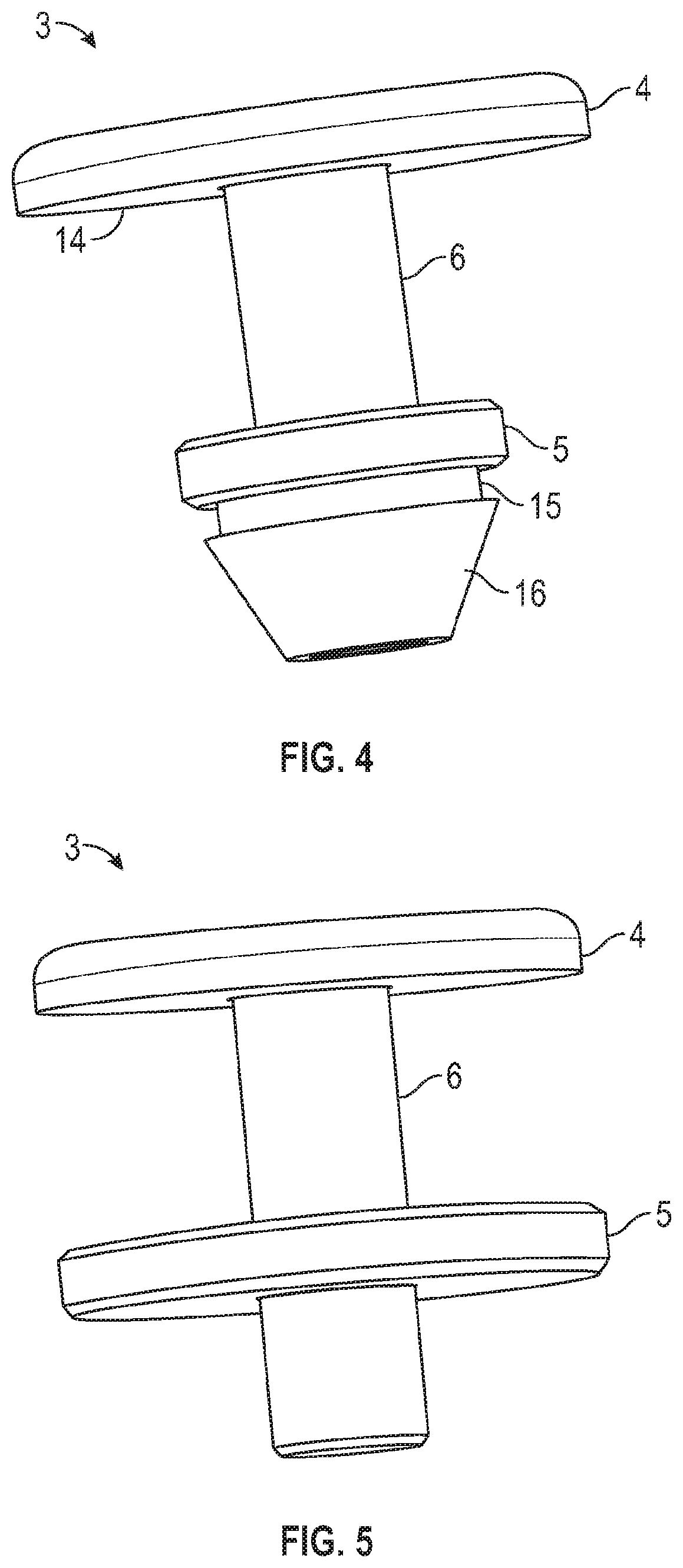
[0036]FIG. 1 shows an ear plug 1 which is supposed to be individually fitted to an ear canal of a person. A first part 20 of the ear plug 1 will be arranged in the ear canal and a second part 21 of the ear plug shown in FIG. 1 will be arranged in the concha region or outside the ear canal. In other embodiments the whole ear plug may be fitted into the ear canal. The ear plug 1 is shaped by a wall 2 made of a resilient material, e.g. silicone. Two EEG electrodes 3 are shown in the ear plug, but there could be three or four. Each EEG electrode comprises a skin contact part 4, which should obtain a good electrical contact with the skin of the person when the ear plug 1 is in use. The skin contact part 4 is arranged on the external side of the housing wall 2. The skin contact part 4 is connected by a connector 6, e.g. a metal pin, through the wall 2 to a supporting member 5 arranged on the inner side of the wall 2. The supporting member 5 may be in the form of a washer. The two electrod...


PUM


Abstract

An ear plug for arrangement in an ear canal includes at least two electrodes for detecting an EEG signal from a skin surface when the ear plug is arranged in the ear canal. The ear plug further includes a housing having an outer wall made from a resilient material, and a signal acquisition circuit. The electrodes are provided with a skin contact part arranged on an outside surface of the housing and connected through the outer wall of the housing to a supporting member on the inner part of the housing. The skin contact part and the supporting member are arranged for clamping the outer wall.

Description

[0001]This application is a continuation-in-part of Application No. PCT / EP2015 / 072691 filed Oct. 1, 2015, the disclosure of which is incorporated by reference herein.BACKGROUND OF THE INVENTION[0002]The present invention relates to an ear plug for detecting bio-electrical signals. The invention relates more particularly to an ear plug for arrangement in an ear canal, where the ear plug comprises at least two electrodes prepared for detecting an EEG signal from a skin surface when the ear plug is arranged in the ear canal. The ear plug also comprises a housing with an outer wall made from a resilient material, and further comprises a signal acquisition circuit. The invention also relates to a method for manufacturing the ear plug.[0003]Bio-electrical signals are here understood to be electrical potential differences across a tissue, organ or cell system or originating from the human body. The best known examples are Electrocardiogram (ECG) signals and Electroencephalogram (EEG) signa...

Claims


Application Information

Patent Timeline
Patent Type & Authority Patents(United States)
IPC IPC(8): A61B5/00A61B5/0478H04R25/00A61B5/296
CPCH04R25/652A61B5/6847A61B5/0478A61B5/6817H04R25/658A61B5/6867A61B2562/125H04R25/65A61B5/291
Inventor ANDERSEN, MIKAEL
Owner T&W ENG
Why Eureka
Try Eureka