Method for polishing artificial tooth and device for polishing artificial tooth

a technology for artificial teeth and polishing methods, which is applied in the field of polishing artificial teeth and a device for polishing artificial teeth, can solve the problems of reduced strength of artificial teeth, poor bite, and difficulty in finishing, and achieve the effects of preventing cracks, reducing strength, and preventing deposition

Active Publication Date: 2020-09-08
FUJI MFG CO LTD
View PDF32 Cites 0 Cited by
  • Summary
  • Abstract
  • Description
  • Claims
  • Application Information

AI Technical Summary

Benefits of technology

[0043]Due to the present invention being configured as described above, the present invention is able to obtain the following significant advantageous effects.
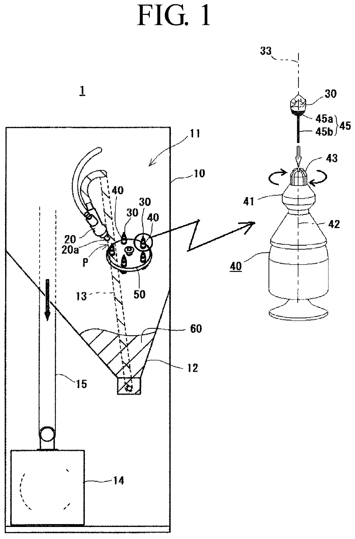
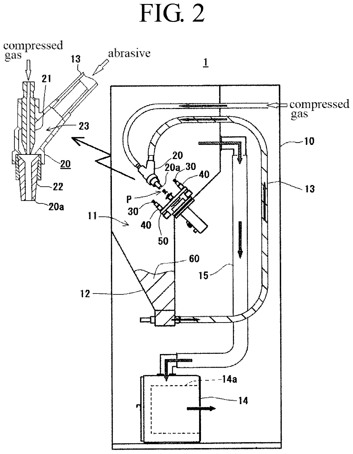
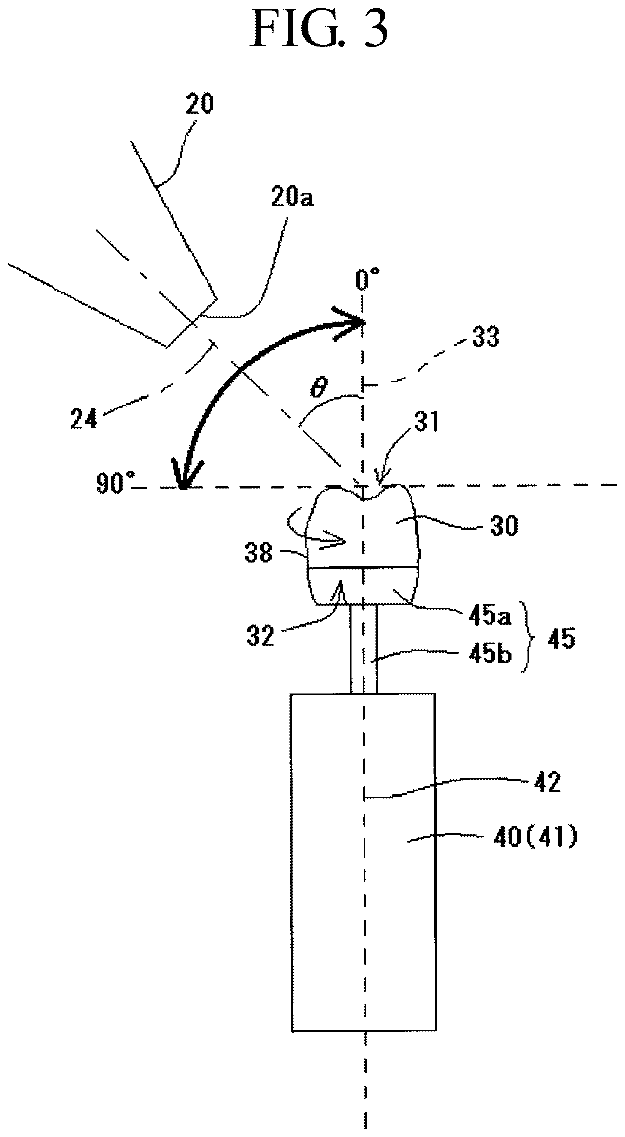
[0044]An artificial tooth 30 to be polished is fixed at a tooth neck 32 side thereof and rotated about a tooth axis 33. Portions from an occlusal portion 31 side to a side surface 38 of the artificial tooth 30 can be polished at the same time by ejecting the abrasives through a blast nozzle 20 having a tip 20a pointing toward the occlusal portion 31 of the rotating artificial tooth 30 and having a central axis 24 inclined at an inclination angle θ of from 0° to 90° with respect to the tooth axis 33.
[0045]Moreover, the abrasives ejected in this manner readily enter even indentations in the surface of the artificial tooth 30, and polishing can be performed uniformly even when the artificial tooth 30 includes indentations and protrusions on its surface. By ejecting the abrasives in the ejection direction described above, a flow of abrasives is generated and the flow moves from the occlusal portion 31 side of the artificial tooth 30 toward the tooth neck 32 side. This flow of abrasives flows over the side surface 38 of the artificial tooth 30, as illustrated in FIG. 4A. This means that the abrasives do not readily enter into the hollow portion 36 of the artificial tooth 30 even when the artificial tooth 30 to be polished is a crown, enabling loose fitting that arises from polishing an internal wall 37 of the hollow portion 36 to be prevented from occurring when fitted.
[0046]Moreover, due to the abrasives that move over the side surface 38 of the artificial tooth 30 as described above moving from the occlusal portion 31 side to the tooth neck 32 side, a margin portion 34 and an end portion (edge 35) of the margin portion 34 can be prevented from being excessively ground. This accordingly enables to prevent a decrease in strength accompanying wall thinning due to over polishing, or a not-flat portion between the edge 35 of the margin portion 34 and an anchor tooth appearing when fitted. This is favorable for the prevention of cracks and breaks occurring after fitting due to a decrease in strength, for the prevention of deposition of plaque accompanying generation of the non-flat portion, and for the prevention of the occurrence of alveolar pyorrhea accompanying such plaque deposition.
[0047]When an elastic abrasive is employed as the abrasive 60, an elastic body that is a configuration member of the elastic abrasive absorbs shock on impact with the artificial tooth 30, facilitating movement (sliding) of the abrasive 60 so as to slide along the surface of the artificial tooth 30. This enables the surface of the artificial tooth 30 to be polished more simply to a glossy finish, mirror finish, or the like, while preventing over polishing. In particular, a configuration in which the central axis 24 of the blast nozzle 20 is inclined with respect to the tooth axis 33 at an inclination angle θ of from 15° to 75° results in the abrasives 60 being incident an angle inclined to both the occlusal portion (occlusal surface) 31 and the side surface 38 of the artificial tooth 30. This facilitates sliding of the abrasives 60 at the surface of the artificial tooth 30, and makes polishing to a mirror finish etc. even easier.
[0048]Furthermore, by moving plural artificial teeth 30 along a common movement path, and placing the tip 20a of the blast nozzle 20 that is common to the plural artificial teeth 30 so as to point toward a treatment position P at a predetermined position on the movement path, a configuration is achieved in which the tip 20a of the blast nozzle 20 at the treatment position P points toward the occlusal portion 31 of the artificial tooth 30 that moved to the treatment position P. This enables plural artificial teeth 30 to be polished in succession, and enables productivity to be greatly improved.

Problems solved by technology

The assessment of finishing is difficult because sometimes such over polishing leads to poor bite when fitted, to a decreased strength of the artificial tooth, etc. occurring, and so on.
Variation arises in finishing precision for each dental technician when manual polishing is performed in such a manner by individual dental technicians, making it difficult to unify and standardize the finished state.
Moreover, polishing operations to polish artificial teeth manually on a one-by-one basis take a long duration, imposing a great burden of labor on the dental technicians.
However, in the above configuration, the abrasives 160 filled in the abrasive tank 104 are in a state of which fluidity of the abrasives 160 are poor during polishing due to adsorption forces between particles.
Moreover, polishing of the inside of the indentations is also difficult to perform since any abrasive that has entered into the indentations tends to remain therein.
This is a cause of the crown 130 falling out or wobbling after fitting.
This results in the overall installation becoming bulky and costly, and increases running costs due to high power consumption.

Method used


Image

  • Method for polishing artificial tooth and device for polishing artificial tooth
  • Method for polishing artificial tooth and device for polishing artificial tooth
  • Method for polishing artificial tooth and device for polishing artificial tooth

Examples


example 1

(1) Example 1

[0120]The surface roughness of artificial teeth as per Example 1 (polishing artificial teeth manufactured from hybrid resin) was measured before and after polishing using a contact needle type of surface roughness measuring instrument (manufactured by Tokyo Seimitsu Co., Ltd.). The results thereof are listed in Table 2 together with the results of observing the state of glossiness with the naked eye.

[0121]

TABLE 2Surface Roughness Before and After Polishing(Artificial Teeth Manufactured from Hybrid Resin)Ra (μm) Before PolishingRa (μm) After PolishingOcclusal Surface0.820.08Side Surface1.730.56GlossinessNoneGood

[0122]It is apparent from the above results that the surface roughness can be greatly improved and polishing can also achieve a state of good glossiness by polishing artificial teeth manufactured from a hybrid resin using the polishing method of the present invention. The finishing polish of the artificial teeth can also be achieved in an extremely short duration ...


PUM

PropertyMeasurementUnit
inclination angleaaaaaaaaaa
temperatureaaaaaaaaaa
inclination angleaaaaaaaaaa

Abstract

An artificial tooth 30 to be polished is fixed at a tooth neck 32 side and rotated about a tooth axis 33. Abrasives, preferably elastic abrasives formed by kneading abrasive grains into or supporting abrasive grains on an elastic material, are ejected together with a compressed gas at an ejection pressure of from 0.1 MPa to 0.5 MPa onto an occlusal portion 31 side of the artificial tooth 30 while the artificial tooth 30 is being rotated. The abrasives are ejected at an inclination angle θ with respect to the tooth axis 33 of the artificial tooth 30 of from 0° to 90°, and preferably from 15° to 75°. Portions on the occlusal portion 31 and side surfaces 38 of the artificial tooth 30 are thereby polished at the same time by the abrasive sliding over these portions.

Description

BACKGROUND OF THE INVENTION1. Field of the Invention[0001]The present invention relates to a method for polishing artificial teeth and a device for polishing artificial teeth. More particularly, the present invention relates to a method for polishing artificial teeth, and a device for polishing artificial teeth, in which blasting is performed by ejecting an abrasive together with a compressed gas.2. Description of the Related Art[0002]After molding an artificial tooth, such as a crown, and before fitting inside the oral cavity of a patient, any surfaces of portions of the artificial tooth that will make contact inside the oral cavity are given a finishing polish to a glossy finish or a mirror finish. This not only makes the appearance more beautiful, but also improves the fitting sensation and enables helps prevent dirt, such as plaque, from being deposited.[0003]Such a finishing polish of artificial teeth is normally performed manually on a one-by-one basis by a qualified dental te...

Claims


Application Information

Patent Timeline
Patent Type & Authority Patents(United States)
IPC IPC(8): A61C17/16A61C3/025A61C5/70A61C13/12A61C19/00A61C13/087
CPCA61C5/70A61C13/12A61C3/025A61C17/16A61C13/087A61C19/007B24B1/00B24B19/00
Inventor MASE, KEIJIISHIBASHI, SHOZOSHIMA, TAKAHIRO
Owner FUJI MFG CO LTD
Why Eureka
Try Eureka