Eureka AIR delivers breakthrough ideas for toughest innovation challenges, trusted by R&D personnel around the world.

Teach mode collision avoidance system and method for industrial robotic manipulators

a robot manipulator and collision avoidance technology, applied in the field of industrial robots, can solve the problems of software “losing confidence” and information not always made available by robot manufacturers, and achieve the effects of preventing collisions, and reducing the speed of the robo

Active Publication Date: 2020-09-08
BATTELLE MEMORIAL INST
View PDF48 Cites 3 Cited by
  • Summary
  • Abstract
  • Description
  • Claims
  • Application Information

AI Technical Summary

Benefits of technology

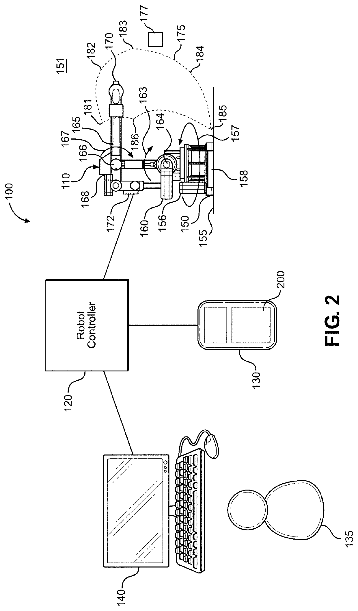
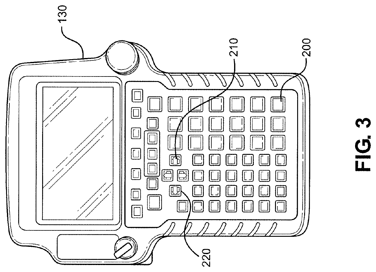
[0013]In one embodiment, a controller is configured to reduce the speed of the robot when any component of the robot approaches the collision geometry such that collisions are prevented while the operator controls the robot directly using the keys in a jog mode. Similarly, the controller is configured to predict the motion of the robot when the operator controls the robot directly in a Cartesian mode, wherein the keys are configured to control the tool center point in Cartesian space.
[0014]In another embodiment, the robot is configured to move according to a program having program steps and acceleration parameters. The controller is further configured to predict the motion of the robot along the predicted path based on a current destination position of a current program step, a speed of the robot, and the acceleration parameters, and to reduce a speed of the robot as the robot approaches the collision geometry along the predicted path such that collisions are prevented.
[0017]The method also preferably includes reducing a speed of the robot as the robot approaches the objects in the environment and preventing collisions while the operator controls the robot directly using the keys in a jog mode. The robot is moved according to a program having program steps and acceleration parameters, and the motion of the robot is predicted based on the current destination position of a current program step, a speed of the robot, and the acceleration parameters. A speed of the robot is reduced as any component of the robot approaches the objects in the environment such that collisions are prevented.
[0018]In another embodiment, the method includes moving the robot according to a program having program steps and predicting the motion of the robot as the robot executes each step of the program. Potential paths of a tool center point of the robot are calculated, and the required robot positions are compared to a history of actual positions. If a path is found to be sufficiently similar to the robot's actual motion, the robot's motion is projected into the future based on the path. A speed of the robot is reduced as any component of the robot is predicted to approach the objects in the environment such that collisions are prevented. A distance between the robot and a nearest point of collision between the robot and the collision geometry is calculated, and the speed of the robot is reduced proportionally to the calculated distance.

Problems solved by technology

Although complete information regarding the robot's future actions is contained in the teach pendant program, this information is not always made accessible by robot manufacturers.
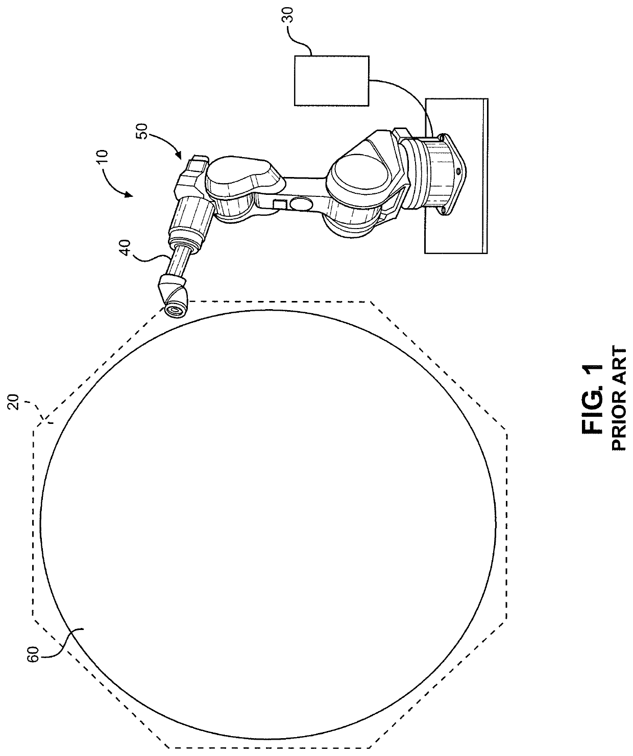
If, however, the robot's motion begins to deviate from the predicted path, the software will “lose confidence” in its prediction and begin to rely on the nearest distance between any part of the robot and a collision geometry, where a collision geometry could be the environment or another part of the robot itself (e.g., it might be possible for the robot to crash the tool it is holding into its own base).

Method used


Image

  • Teach mode collision avoidance system and method for industrial robotic manipulators
  • Teach mode collision avoidance system and method for industrial robotic manipulators
  • Teach mode collision avoidance system and method for industrial robotic manipulators

Examples


Embodiment Construction

[0027]Detailed embodiments of the present invention are disclosed herein. However, it is to be understood that the disclosed embodiments are merely exemplary of the invention that may be embodied in various and alternative forms. The figures are not necessarily to scale, and some features may be exaggerated or minimized to show details of particular components. Therefore, specific structural and functional details disclosed herein are not to be interpreted as limiting, but merely as a representative basis for teaching one skilled in the art to employ the present invention. The foregoing description of the figures is provided for a more complete understanding of the drawings. It should be understood, however, that the embodiments are not limited to the precise arrangements and configurations shown. Although the design and use of various embodiments are discussed in detail below, it should be appreciated that the present invention provides many inventive concepts that may be embodied ...


PUM


Abstract

A robot system includes a robot, a teach pendant having an operator interface, and a robot controller with a computer and associated hardware and software containing a virtual representation of the robot and the environment. The system employs a method for avoiding collisions including moving a manipulator arm along an actual path in an environment containing objects constituting collision geometry. Operator input is entered into the teach pendant, whereby the operator is able to directly control motion of the robot along the actual path. A recent history of the motion of the robot is recorded, and a predicted path of the robot is developed based on the input entered into the teach pendant and the recent history of the motion of the robot. Real-time collision checking between the predicted path and the collision geometry is performed while the operator manually controls the robot using the teach pendant.

Description

CROSS-REFERENCE TO RELATED APPLICATIONS[0001]This application claims the benefit of U.S. Provisional Application No. 62 / 485,159, which was filed on Apr. 13, 2017 and titled “Teach Mode Collision Avoidance System and Method for Industrial Robotic Manipulators”. The entire content of this application is incorporated herein by reference.FIELD OF THE INVENTION[0002]The present invention pertains to the art of industrial robots and more specifically to controllers for robots operating in a manufacturing environment that prevent the robots from colliding with surrounding objects in their workspace.BACKGROUND OF THE INVENTION[0003]Robots are now commonplace in a typical manufacturing environment. Industrial robots are used in many industries for manufacturing products. For example, in the aerospace industry, robots have been employed to work on components such as wing assemblies and fuselages. Robots, provided with various end effectors and tools, are now moving work pieces around the manu...

Claims


Application Information

Patent Timeline
Patent Type & Authority Patents(United States)
IPC IPC(8): B25J9/16G05B19/409G05B19/427
CPCB25J9/1676B25J9/163B25J9/1671G05B19/409G05B19/427G05B2219/35471G05B2219/39082G05B2219/39433G05B2219/39434G05B2219/39443G05B2219/39445G05B2219/40311G05B2219/40317G05B2219/49158
Inventor KRASNY, DARRENSCHMID, ZACHARY
Owner BATTELLE MEMORIAL INST
Why Eureka
Eureka Blog
Learn More