
Vehicle having cooling arrangement disposed below floor surface

a cooling arrangement and floor surface technology, applied in the field of vehicles, can solve the problem of long oil passage, and achieve the effect of enhancing the cooling performance of the radiator by effectively utilizing the dead space around the motor

Active Publication Date: 2020-09-08
HONDA MOTOR CO LTD
View PDF16 Cites 1 Cited by
  • Summary
  • Abstract
  • Description
  • Claims
  • Application Information

AI Technical Summary

Benefits of technology

The present invention provides a vehicle that effectively utilizes a space around the motor to place a radiator and ensures cooling performance of the radiator. By placing the radiator in the gap between the motor and battery, it can be easily positioned without taking up excessive space. Additionally, placing the radiator below the floor surface improves its cooling performance.

Problems solved by technology

However, when a radiator of the ATF cooler is to be disposed at the forefront portion of the engine compartment of the vehicle, the oil passage becomes long in the vehicle in which the transmission is disposed in a rear portion of the vehicle.
Meanwhile, in recent years, an electric motor has been used as a drive source in an electric vehicle or a hybrid vehicle, and it is a very important problem to ensure a cooling performance of the radiator in light of efficiently cooling the electric motor.

Method used


Image

  • Vehicle having cooling arrangement disposed below floor surface
  • Vehicle having cooling arrangement disposed below floor surface

Examples


Embodiment Construction

[0014]Hereinafter, a vehicle according to an embodiment of the present invention will be described with reference to the accompanying drawings.

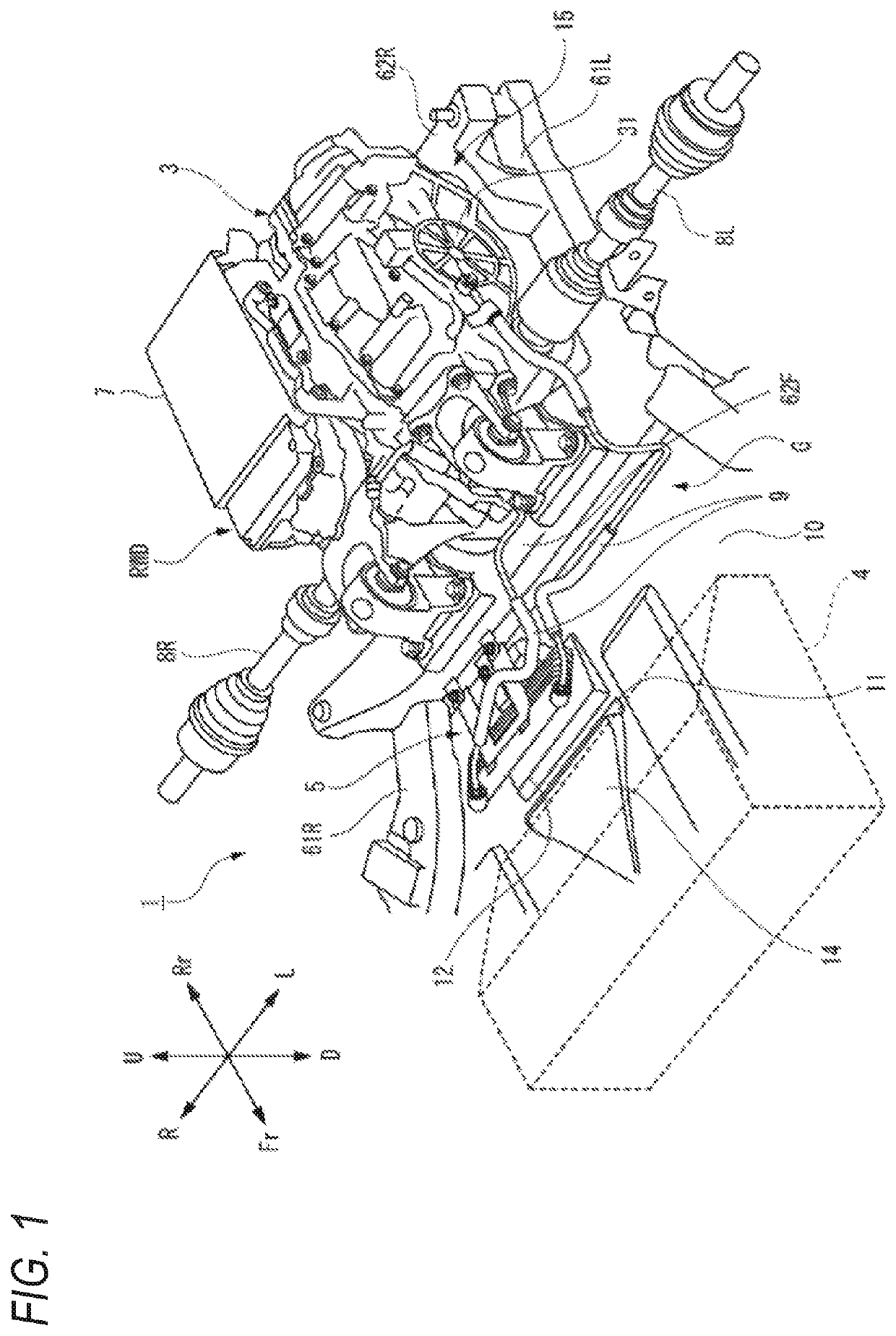
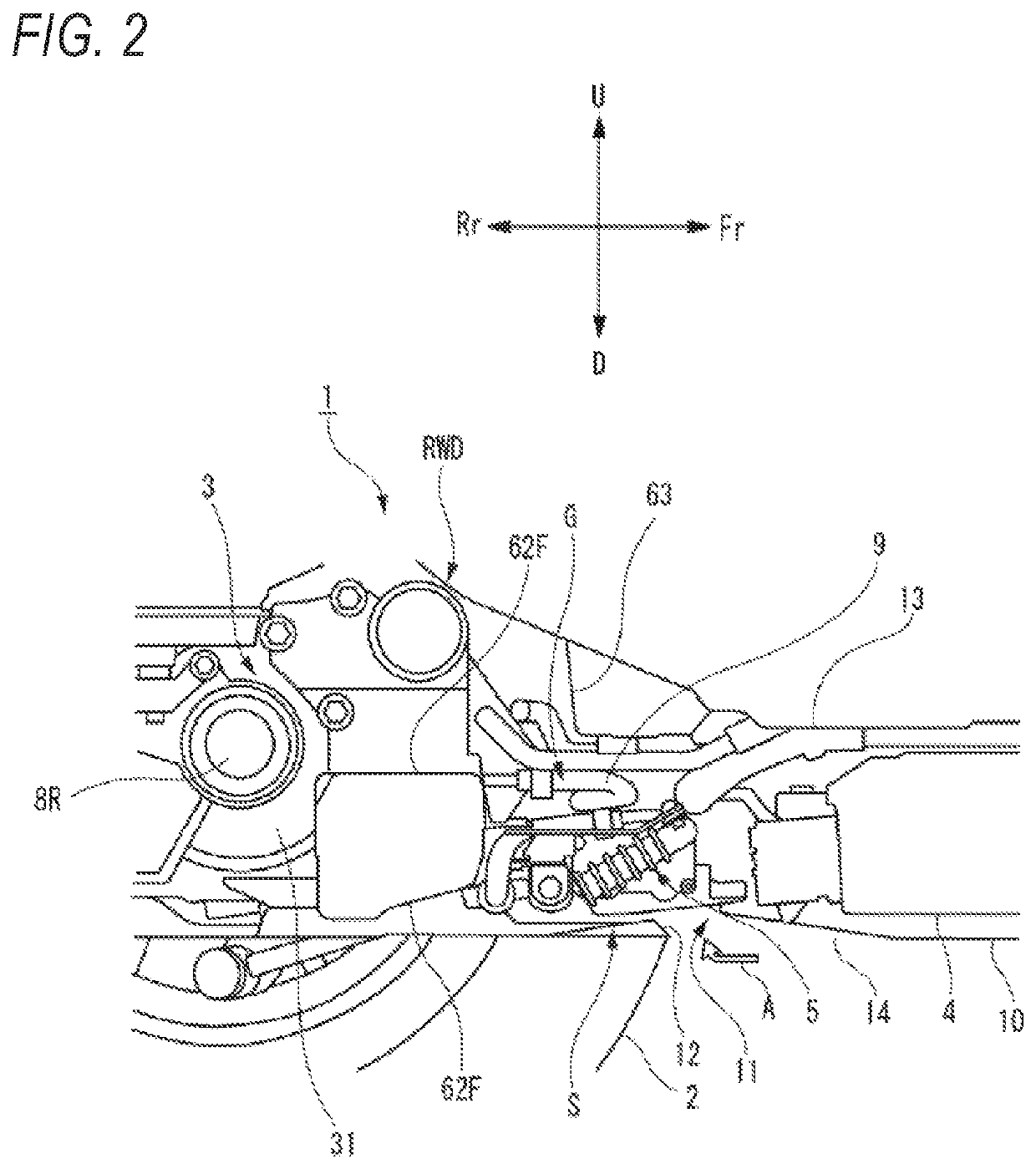
[0015]As shown in FIGS. 1 and 2, a vehicle 1 according to an embodiment of the present invention includes a rear wheel drive device RWD at a rear portion of the vehicle 1. The rear wheel drive device RWD includes a motor 3 configured to drive a vehicle wheel 2 that is a rear wheel, a battery 4 configured to supply electric power to the motor 3, a radiator 5 configured to exchange heat between a coolant for cooling the motor 3 and a traveling wind (outside air) A, and an inverter 7 configured to convert the electric power between the motor 3 and the battery 4.

[0016]The motor 3 is supported by a front frame member 62F and a rear frame member 62R in a state of being accommodated below a floor surface 13 in a substantially rectangular motor accommodating portion 15 defined by a pair of side members 61L, 61R extending in a front-rear direction and...


PUM


Abstract

A vehicle includes a motor configured to drive a vehicle wheel, a battery configured to supply electric power to the motor, and a radiator configured to exchange heat between a coolant for cooling the motor and outside air. The radiator is disposed below a floor surface of the vehicle and in a gap between the motor and the battery in a front-rear direction of the vehicle.

Description

CROSS-REFERENCE TO RELATED APPLICATIONS[0001]This application is based on and claims priority under 35 USC 119 from Japanese Patent Application No. 2018-062567 filed on Mar. 28, 2018.TECHNICAL FIELD[0002]The present invention relates to a vehicle including a motor and a battery.BACKGROUND ART[0003]JP-A-2001-253257 describes an automatic transmission fluid (ATF) cooler in which a heat exchanger, which exchanges heat between an engine coolant and an ATF supplied circularly to a transmission, is disposed inside a clutch case, and an engine cooler radiator and the heat exchanger are connected by an oil passage. JP-A-2001-253257 does not describe where the engine cooler radiator is disposed, but in a general vehicle, the engine cooler radiator is disposed at a forefront portion of an engine compartment of the vehicle with good cooling efficiency.[0004]However, when a radiator of the ATF cooler is to be disposed at the forefront portion of the engine compartment of the vehicle, the oil pa...

Claims


Application Information

Patent Timeline
Patent Type & Authority Patents(United States)
IPC IPC(8): B60K1/04B60K11/04B60K11/08B60K1/00B60K11/02
CPCB60K1/04B60K1/00B60K11/04B60K11/08B60Y2400/61B60K2001/001B60K2001/006B60K11/02B60K2001/0438
Inventor TAKAI, KEISUKEKOGA, YUJIKONISHI, YOSHIAKITSUCHIHASHI, MAKOTO
Owner HONDA MOTOR CO LTD
Learn More