Panel for use in a deployable and cantilevered solar array structure

a solar array and cantilever technology, applied in the direction of pv power plants, transportation and packaging,cosmonautic vehicles, etc., can solve the problems of increasing the area moment of inertia of the area, limiting the distance that the panel can extend away from the support structure, and not all of the solar cells supported by the panel are either functional or only marginally functional, etc., to achieve the effect of increasing the area moment of inertia

Active Publication Date: 2020-09-15
M M A DESIGN
View PDF83 Cites 4 Cited by
  • Summary
  • Abstract
  • Description
  • Claims
  • Application Information

AI Technical Summary

Benefits of technology

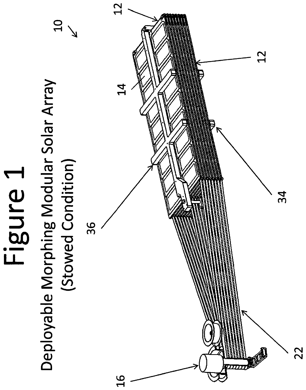
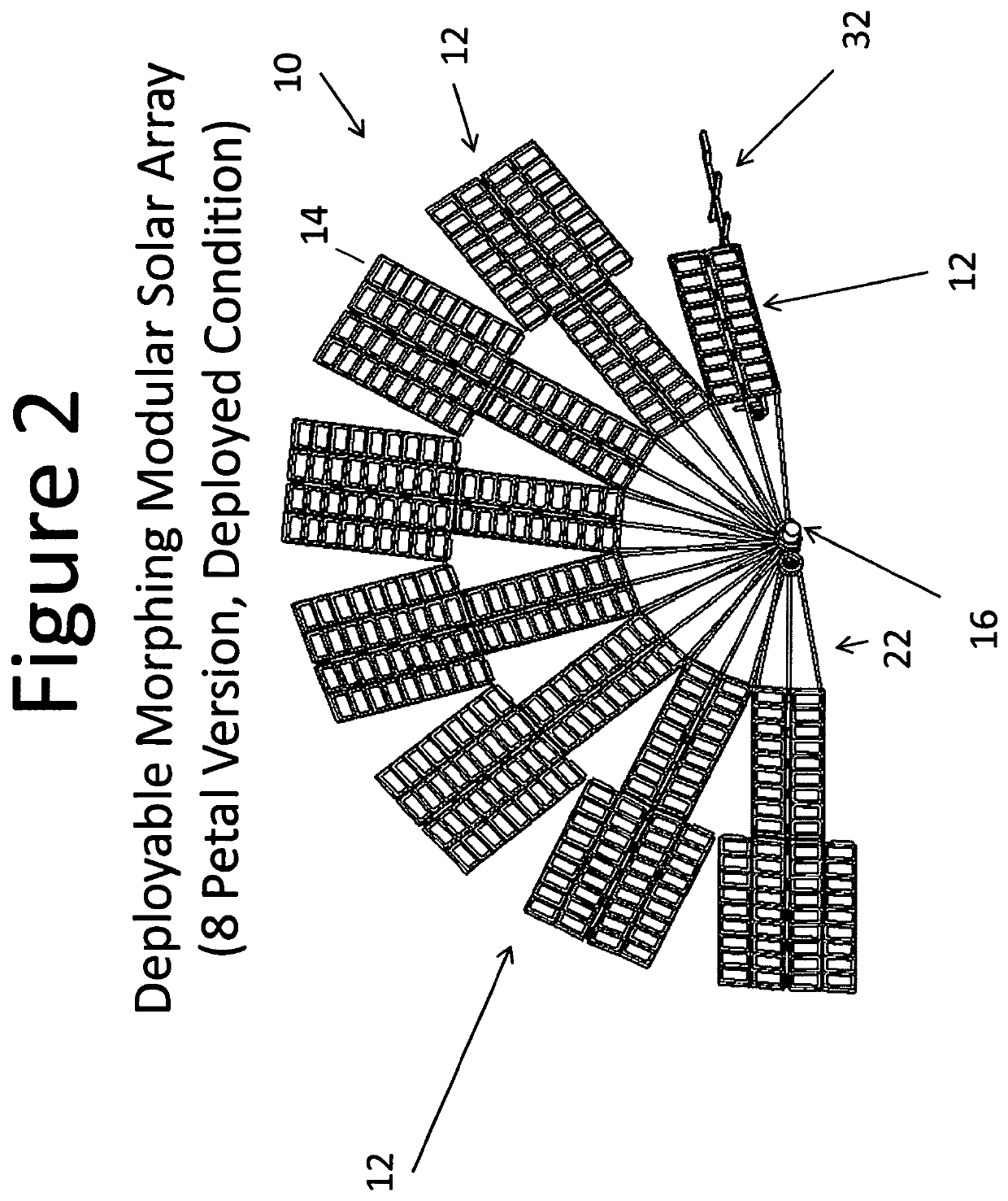
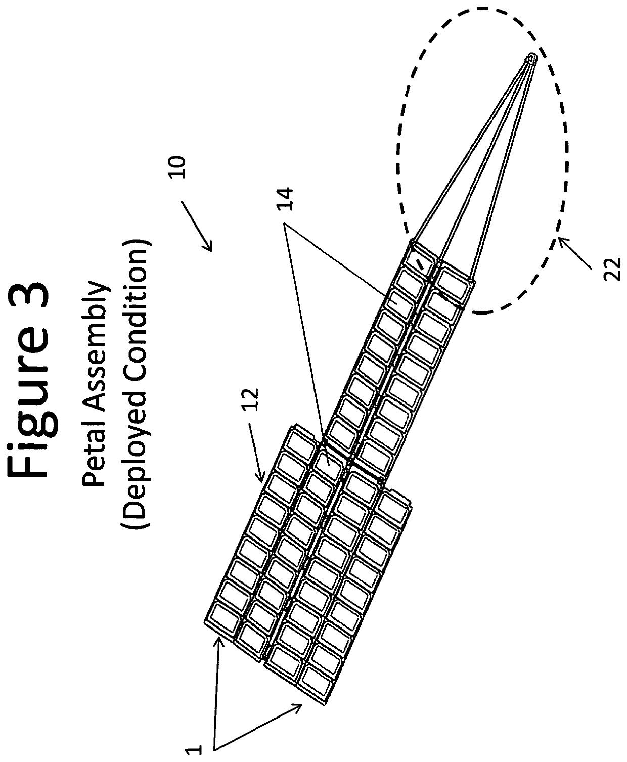
[0006]The present invention is a Deployable Modular Morphing Solar Array (DMMSA). The array is notionally simple, it uses a spring powered Root Staging and Deployment Mechanism (RSDM) that fan deploys structural elements similar to daisy petals that each perform a sequential secondary deployment. The stowed petals are folded when the system is stowed for launch on a spacecraft and unfold to a more structurally ideal configuration once deployed. The fan deployment moves the petals into position to be MORPHED-Deployed then locates them in positions ideal for gathering sun light. The petal assemblies are composed of a yoke that attaches to a Morphing Modular Solar Power Assembly, or assemblies (DMMSPA) that unfurl to form the petal assemblies upon beginning to fan deploy from the spacecraft. The DMMSA system comprises a Root Staging and Deployment Mechanism (RSDM) mounted to the spacecraft. The RSDM positions the stowed DMMSA 90 degrees from the spacecraft, staging it for fan deployment. Petal assemblies are attached to the RSDM by a yoke structure with each petal assembly having at least one DMMSPA secured thereon. Each DMMSPA elastically morphs to a slight V-configuration once deployed. This elastic flexing of the DMMSPA panel to a V cross section increases the area moment of inertia of the panel by orders of magnitude and hence the petal assemblies deployed natural frequency accordingly.

Problems solved by technology

In such a stowed state, most and potentially all of the solar cells supported by the panels are either non-functional or only marginally functional.
However, the cantilever approach also limits the distance that the panel can extend away from the support structure and, as such, the area of a panel that can support a solar cell or cells.
More specifically, as the distance between the supported end of the panel and the free end of the panel increases for a panel made of a given material and having given dimensions, the panel will increasingly bend or deform.
This bending or deformation can be significant enough that the solar cell or cells associated with the panel cannot all be positioned to provide the needed power or the panel exceeds its stress limit and fails.

Method used


Image

  • Panel for use in a deployable and cantilevered solar array structure
  • Panel for use in a deployable and cantilevered solar array structure
  • Panel for use in a deployable and cantilevered solar array structure

Examples


second embodiment

[0063]With reference to FIGS. 15, 16, 17A, and 17B, a panel 100 suitable for use or adaptable for use in a deployable and cantilevered solar array structure is described. The panel 100 exhibits a high moment of inertia and a high stiffness that allows the panel to extend farther, or to be used in combination with other panels to extend farther, in a cantilevered solar array structure than would be possible with a comparable planar panel. By being able to extend farther in a cantilevered solar array structure, the panel or combination of panels is capable of providing a greater amount of surface area that can be occupied by solar cells than would be possible with a comparable planar panel. The panel 100 is capable of being used with a broad range of deployable and cantilevered solar array structures. For instance, the panel 100 is capable of being used in deployable and cantilevered solar array structures that only employ a single panel or that employ several of the panels. With resp...

first embodiment

[0075]With reference to FIGS. 18A-18B, 19, and 20, a hinge 130 that: (a) accommodates rotation of the panel 100 about hinge line that is straight when the panel is in the stowed state and bent when the panel is in the deployed state is described and (b) engages another structure of a deployable and cantilevered solar array structure with components that do not move in any transition between the stowed and deployed states of the panel. As such, the hinge 130 must accommodate three degrees of freedom, two rotational and one translational. One of the rotational degrees of freedom is associated with rotation of the panel 100 relative to the other structure to which the panel is connected by the hinge. The other rotational degree of freedom and the translational degree of freedom are associated with the first and second planar panel sections 108A, 108B rotating with respect to one another between the stowed and deployed states. The translational degree of freedom relates to points on the...


PUM


Abstract

A panel structure for use in a deployable and cantilevered solar array structure is provided. A panel includes first and second planar panel sections and an intermediate panel section connecting the first and second sections. The planar panel sections are capable of being situated with respect to one another so as to have a V-tent-like shape when the panel is in a deployed state and to be coplanar when the panel is in a stowed state. When in the V-tent-like shape, the intermediate section of the panel extends in a straight line that is collinear or parallel to the longitudinal axis of the cantilevered solar array structure when deployed. The V-tent-like shape produces A panel structure that has a relatively high moment of inertia, is stiff, and can provide a large area for supporting solar cells.

Description

CROSS REFERENCE TO RELATED APPLICATIONS[0001]This patent application is a continuation-in-part of U.S. patent application Ser. No. 13 / 199,430, filed Aug. 30, 2011, now U.S. Pat. No. 8,814,099.FIELD OF THE INVENTION[0002]The invention relates to a deployable and cantilevered solar array structure that has particular utility in association with a spacecraft and, more specifically, to a panel structure used in such a deployable and cantilevered solar array structure.BACKGROUND OF THE INVENTION[0003]Generally, one type of deployable solar array structure includes one or more panels that each support one or more solar cells and a deployment structure for transitioning the panels from a stowed / undeployed state to an unstowed / deployed state. In the stowed state, the panel / panels is / are typically disposed in a predefined space and orientation such that the solar cells associated with the panel / panels are either not functional or marginally functional. For example, a deployable solar array s...

Claims


Application Information

Patent Timeline
Patent Type & Authority Patents(United States)
IPC IPC(8): B64G1/44H02S30/10B64G1/22H02S30/20
CPCH02S30/10H02S30/20B64G1/443B64G1/222H02S10/40Y02E10/50
Inventor HARVEY, THOMAS JEFFREYHARVEY, TOBY JUSTINVANHALLE, RYAN M.
Owner M M A DESIGN
Why Eureka
Try Eureka