Laminated-barrel structure for use in a stator-type power generator

Inactive Publication Date: 2016-11-03
GE ENERGY POWER CONVERSION TECH
View PDF10 Cites 6 Cited by
  • Summary
  • Abstract
  • Description
  • Claims
  • Application Information

AI Technical Summary

Benefits of technology

[0015]The barrel increases a second moment of area of the stator portion of the power generator, without adding a large mass to the stator-based gen

Problems solved by technology

These direct-drive permanent magnet generators include bulky and heavy stator structures or frames.
Conventional stators are at times unable to absorb the inputs, as needed, and resonate undesirably.
Unwanted resonation can result especially when the stator is even slightly misaligned, or its mass misdistributed.
The unwanted resonation may create at least intermittent noise pollution to an environment in which the generator is used (e.g., a city neighborhood or cou

Method used


Image

  • Laminated-barrel structure for use in a stator-type power generator
  • Laminated-barrel structure for use in a stator-type power generator
  • Laminated-barrel structure for use in a stator-type power generator

Examples


Embodiment Construction

[0028]While exemplary embodiments are described herein with illustrative embodiments for particular implementations, it should be understood that the technology is not limited thereto. Those skilled in the art with access to the teachings provided herein will recognize additional modifications, applications, and embodiments within the scope thereof, and additional fields in which the barrel structure described herein would be of significant utility.

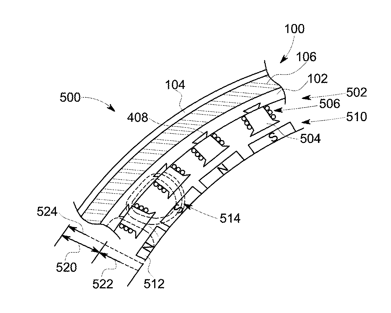
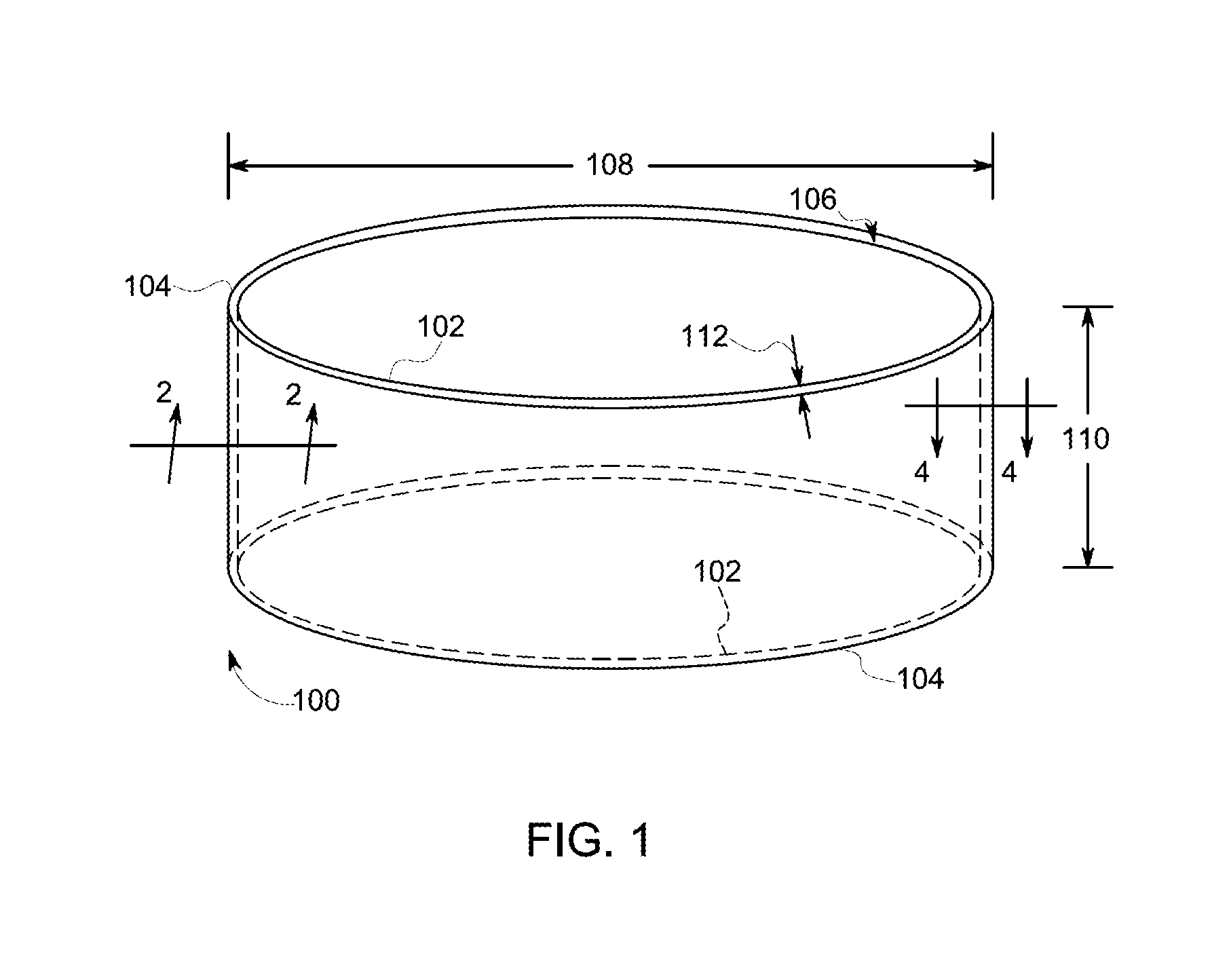
[0029]Now turning to the figures, and more particularly the first figure, FIG. 1 is an skematic illustration of a barrel structure 100 for use with a stator system of a power generator. The power generator can be, for instance, a direct-drive permanent magnet generator (DD PMG).

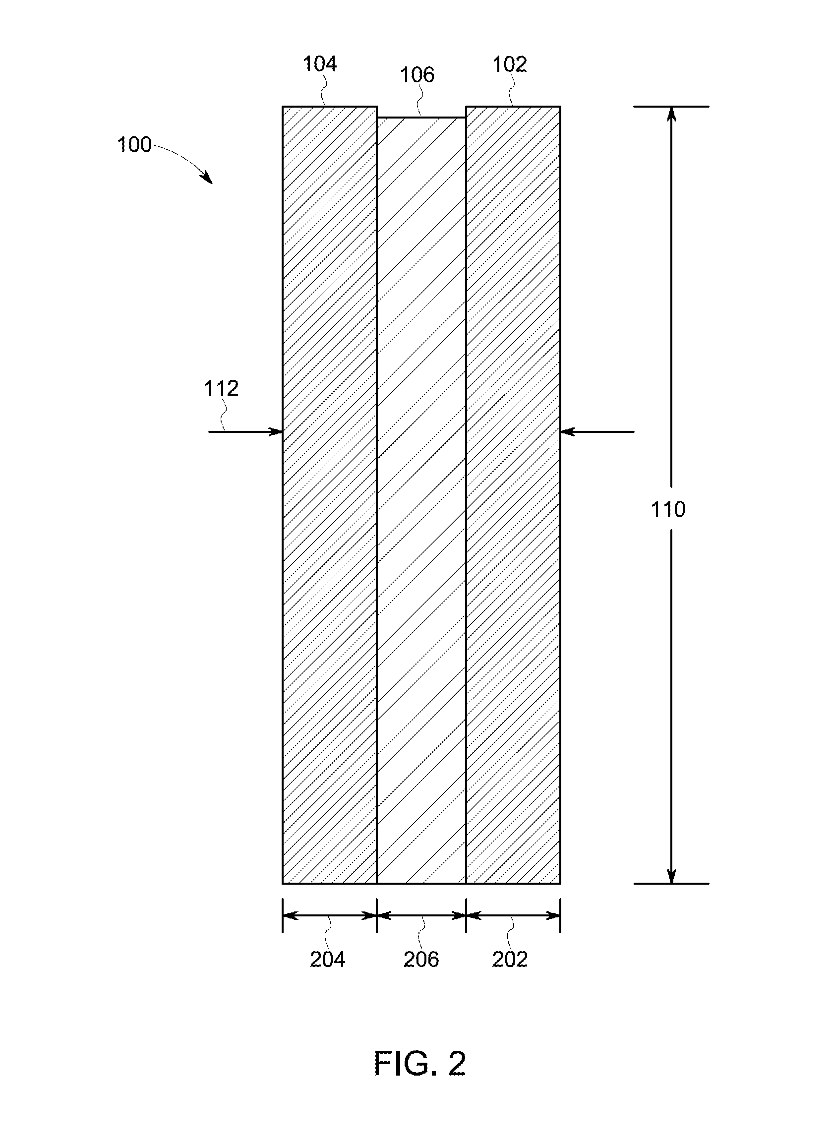
[0030]The barrel structure 100 includes an inner component, or ring, 102, an outer component, or ring, 104, and an intermediate component, or ring, 106. The intermediate ring 106 is shown in greater detail in FIGS. 2 and 4.

[0031]The barrel structure 100 has a gener...


PUM


Abstract

A laminated-barrel structure for use in a permanent-magnet power-generation system is described. The structure includes a rigid outer ring, a rigid inner ring being concentric with and positioned within the rigid outer ring, and a damping intermediate ring positioned between the rigid outer ring and the rigid inner ring. The intermediate ring can include polymer and the rigid rings can include metal. The rigid inner ring can include recesses for receiving stator components of the power-generation system.

Description

TECHNICAL FIELD[0001]The present disclosure relates generally to power generation. More particularly, the present disclosure relates to a laminated-barrel structure for use in a permanent-magnet power generator.BACKGROUND[0002]Large direct-drive permanent magnet generators are used to generate power in applications such as wind turbines. These direct-drive permanent magnet generators include bulky and heavy stator structures or frames.[0003]The large-scale stator frames must withstand operational inputs including shock, torsion, and vibrations. Conventional stators are at times unable to absorb the inputs, as needed, and resonate undesirably. Unwanted resonation can result especially when the stator is even slightly misaligned, or its mass misdistributed.[0004]The unwanted resonation may create at least intermittent noise pollution to an environment in which the generator is used (e.g., a city neighborhood or country side), and can harm generator components and intra-generator conne...

Claims


Application Information

Patent Timeline
IPC IPC(8): H02K5/24H02K1/27H02K1/14
CPCH02K5/24H02K1/27H02K1/146H02K1/185H02K21/02H02K1/04H02K1/148H02K1/187H02K7/1838H02K15/022H02K15/12Y02E10/72F16F1/38H02K7/183
Inventor BRADLEY, STUART
Owner GE ENERGY POWER CONVERSION TECH
Why Eureka
Try Eureka