Optical connector

a technology of optical connectors and connectors, applied in the field of optical connectors, can solve problems such as performance decline, and achieve the effect of excellent light transmission efficiency and high accuracy

Active Publication Date: 2020-09-22
YAZAKI CORP
View PDF8 Cites 0 Cited by
  • Summary
  • Abstract
  • Description
  • Claims
  • Application Information

AI Technical Summary

Benefits of technology

[0005]The present invention has been made in view of the above-described circumstances, and an aspect thereof is to provide an optical connector in which optical axes of a lens and an optical element are aligned with high accuracy to obtain excellent light transmission efficiency.
[0017]According to the optical connector having the configuration (1), if the FOT is biased toward the lens body by the biasing portion; the FOT is disposed in parallel to the lens body with a uniform gap therebetween in the direction along the optical axis of the optical element by the plurality of abutment convex portions. Therefore, even if the FOT undergoes deformation which is bending, warpage, or the like, the FOT can be corrected and disposed in parallel to the lens body, and the optical axis of the optical element of the FOT can be aligned with high accuracy without being inclined relative to the optical axis of the lens portion of the lens body. Accordingly, the optical loss generated between the lens portion and the optical element can be minimized, and excellent light transmission efficiency can be obtained. Further; the lens body, to which the FOT is pressed, is pressed against the housing in the containing portion. Therefore, even if the lens body undergoes deformation which is bending, warpage, or the like, the lens body is also corrected together with the FOT, and the inclination of the optical axis of the lens portion of the lens body can also be reduced or prevented.
[0018]According to the optical connector having the configuration (2), at least three of the abutment convex portions are arranged around the periphery of each of the light emitting side transmission part between the light emitting side lens portion and the light emitting side FOT and the light receiving side transmission part between the light receiving side lens portion and the light receiving side FOT. Therefore, the light emitting side lens portion and the light emitting side FOT serving as the light emitting side transmission part, and the light receiving side lens portion and the light receiving side FOT serving as the light receiving side transmission part can be disposed in parallel with high accuracy. Accordingly, the optical axes of the light emitting side lens portion and the light emitting side FOT and the optical axes of the light receiving side lens portion and the light receiving side FOT can be aligned with high accuracy. Therefore, the optical loss generated in the light emitting side transmission part and the light receiving side transmission part can be minimized.
[0019]According to the optical connector having the configuration (3), the light emitting side FOT and the light receiving side FOT of the FOT are biased by the biasing portion on the optical axis, so that the optical axes of the light emitting side lens portion and the light emitting side FOT and the optical axes of the light receiving side lens portion and the light receiving side FOT can be aligned with high balance and high accuracy.
[0020]According to the present invention, it is possible to provide an optical connector in which optical axes of a lens and an optical element are aligned with high accuracy to obtain excellent light transmission efficiency.

Problems solved by technology

If the deviation of the optical axis occurs, an optical loss between the lens and the optical element increases, which leads to a decrease in performance.

Method used


Image

  • Optical connector
  • Optical connector
  • Optical connector

Examples


Embodiment Construction

[0034]Hereinafter, embodiments according to the present invention will be described with reference to the drawings.

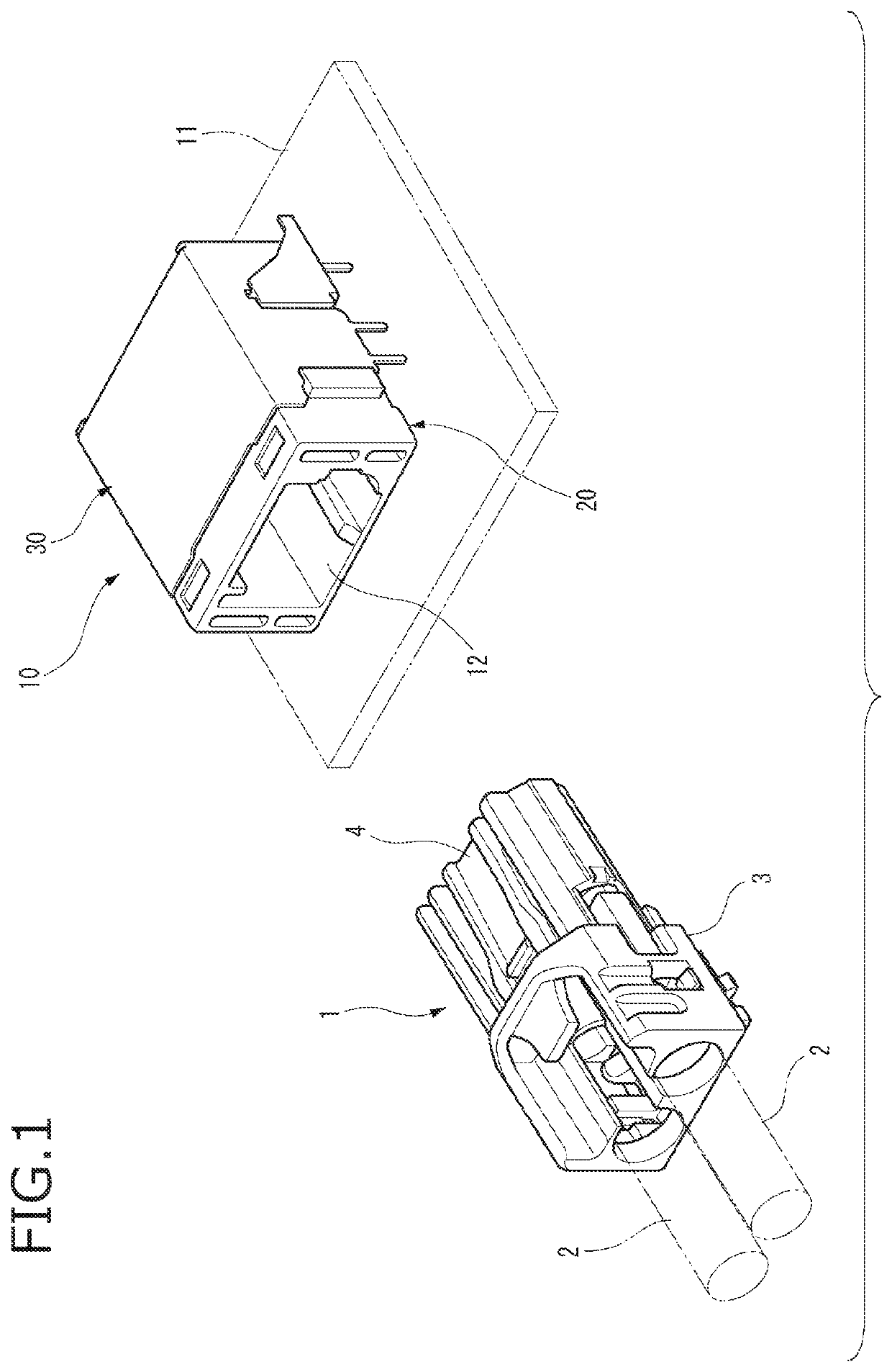
[0035]FIG. 1 is a perspective view of an optical connector according to an embodiment and a mating side optical connector.

[0036]As illustrated in FIG. 1, an optical connector 10 according to the present embodiment is a receptacle optical connector to which a mating side optical connector 1, which is a plug connector, is fitted. The optical connector 10 is mounted on a circuit board 11, and the mating side optical connector 1 is fitted into a fitting recessed portion 12 in the optical connector 10.

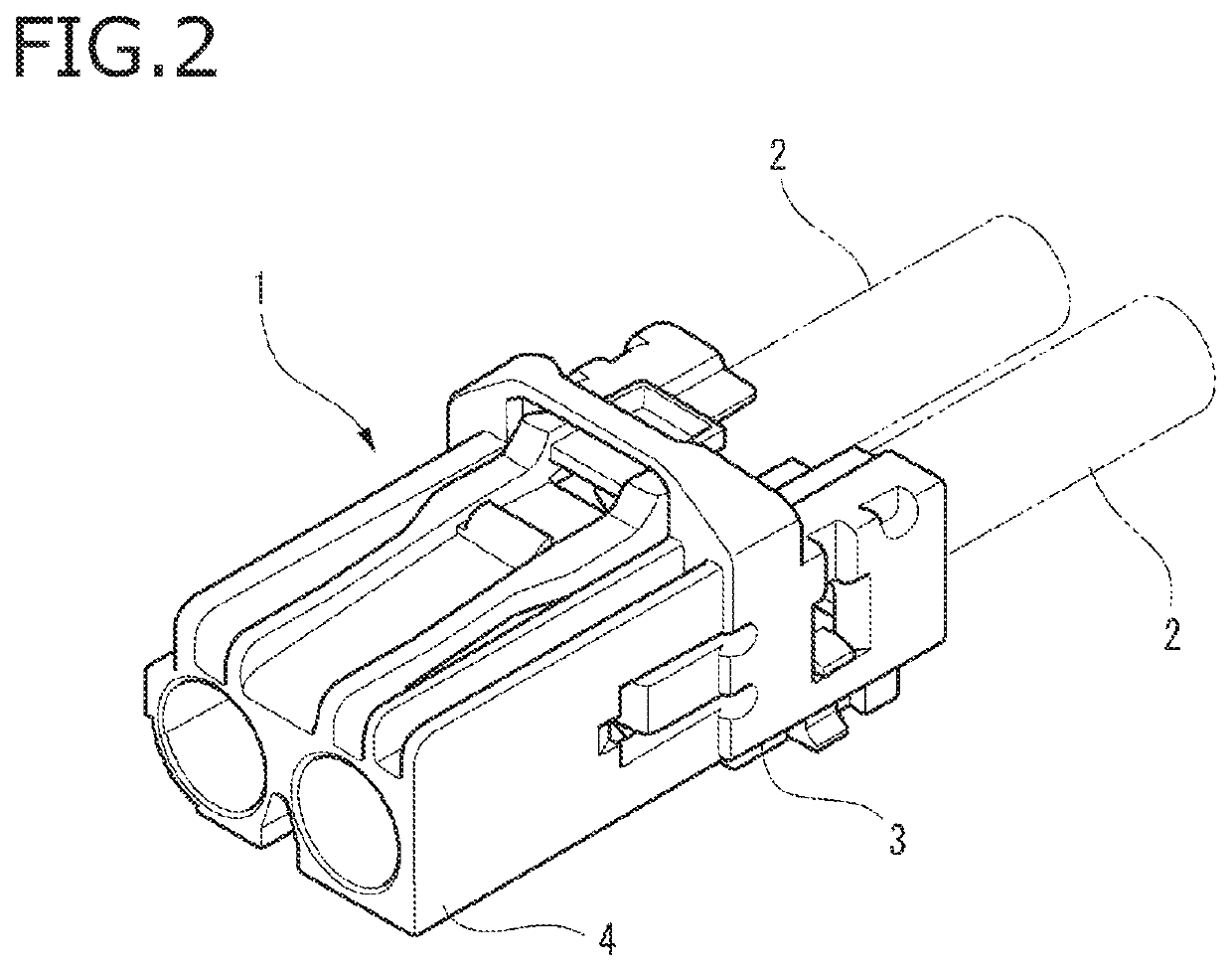
[0037]FIG. 2 is a perspective view of the mating side optical connector.

[0038]As illustrated in FIG. 2, the mating side optical connector 1 includes a housing 3 connected to an end portion of an optical fiber 2. A front end of the housing 3 is a fitting portion 4, and the fitting portion 4 is fitted into the fitting recessed portion 12 of the optical connector 10. Accordingly, ...


PUM

PropertyMeasurementUnit
heightaaaaaaaaaa
opticalaaaaaaaaaa
optical lossaaaaaaaaaa

Abstract

An optical connector includes a lens body having a lens portion, a fiber optic transceiver having an optical element, a housing, an biasing portion configured to bias the fiber optic transceiver toward the lens portion, and a plurality of abutment convex portions provided on at least one of the lens body and the fiber optic transceiver such that the fiber optic transceiver biased toward the lens body by the biasing portion is arranged in parallel to the lens body with a uniform gap between the fiber optic transceiver and the lens body in a direction along an optical axis of the optical element.

Description

CROSS REFERENCE TO RELATED APPLICATIONS[0001]This application is based on Japanese Patent Application (No. 2018-150794) filed on Aug. 9, 2018, the contents of which are incorporated herein by reference.BACKGROUND OF THE INVENTION1. Field of the Invention[0002]The present invention relates to an optical connector.2. Description of the Related Art[0003]An optical connector used in an optical communication field includes a fiber optic transceiver (FOT) having a light emitting element and a light receiving element, and a lens disposed to face the light emitting element and the light receiving element of the FOT (for example, see JP-A-2013-4437). In the optical connector, an optical signal from the light emitting element of the FOT is guided to an optical fiber of a mating optical connector through the lens, and an optical signal from the optical fiber of the mating optical connector is guided to the light receiving element through the lens.[0004]When a resin FOT having a light emitting ...

Claims


Application Information

Patent Timeline
Patent Type & Authority Patents(United States)
IPC IPC(8): G02B6/36G02B6/38G02B6/42G02B6/32
CPCG02B6/4228G02B6/4292G02B6/3821G02B6/32G02B6/4204G02B6/4244G02B6/4245G02B6/4246G02B6/426G02B6/4277G02B6/428
Inventor HIKOSAKA, TOMOHIRO
Owner YAZAKI CORP
Why Eureka
Try Eureka