Distributed equipment abnormality detection system for monitoring physical amounts of equipments and detecting abnormality of each equipment

a technology of abnormality detection and equipment, applied in power supply testing, program control, instruments, etc., can solve the problem that abnormal battery cells may constitute an obstacle to the entire battery system, and achieve the effect of reducing communication amount and calculation amount and low cos

Active Publication Date: 2020-09-22
MITSUBISHI ELECTRIC CORP
View PDF17 Cites 1 Cited by
  • Summary
  • Abstract
  • Description
  • Claims
  • Application Information

AI Technical Summary

Benefits of technology

[0015]Thus, according to the distributed equipment abnormality detection system according to the present invention, it is possible to provide a distributed equipment abnormality detection system that monitors a plurality of equipments and detects an abnormality, the distributed equipment abnormality detection system with low cost being capable of reducing the communication amount and the calculation amount as compared with prior art.

Problems solved by technology

When there is even only one battery cell in an abnormal state, the abnormal battery cell may constitute an obstacle to the entire battery system and the operation of equipment connected thereto.

Method used


Image

  • Distributed equipment abnormality detection system for monitoring physical amounts of equipments and detecting abnormality of each equipment
  • Distributed equipment abnormality detection system for monitoring physical amounts of equipments and detecting abnormality of each equipment
  • Distributed equipment abnormality detection system for monitoring physical amounts of equipments and detecting abnormality of each equipment

Examples


first embodiment

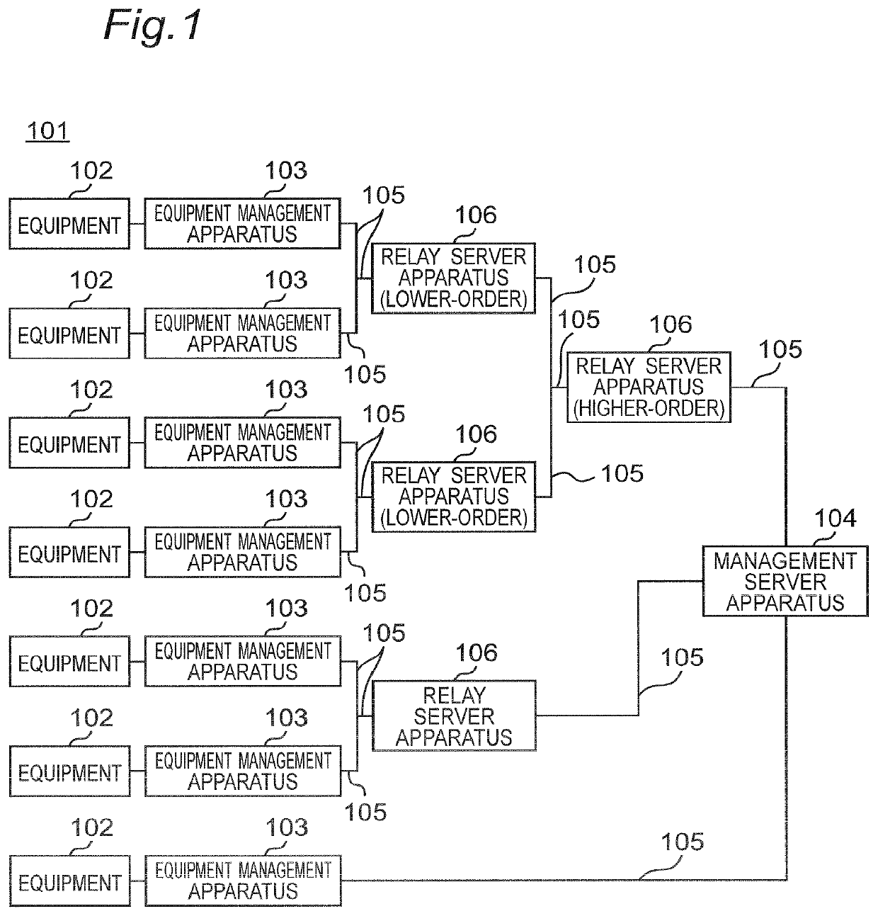
[0038]FIG. 1 is a block diagram illustrating an entire configuration of a distributed equipment abnormality detection system 101 according to a first embodiment of the present invention. As illustrated in FIG. 1, the distributed equipment abnormality detection system 101 according to the first embodiment is configured to include: equipment management apparatuses 103 which are respectively connected to a plurality of equipments 102 of substantially the same type and provided for the respective equipments 102; a management server apparatus 104 which totally controls the entire system; a relay server apparatus 106; and a communication line 105 which connects the equipment management apparatuses 103, the relay server apparatus 106, and the management server apparatus 104. It is noted that the equipments 102 of substantially the same type perform substantially similar operations and have a physical amount as a state value indicating a state such as a normal state or an abnormal state. In...

second embodiment

[0100]A second embodiment according to the present invention is applied to a case in which it is possible to define and measure input and output data (input and output values) of the equipment 102 instead of the physical amount of the equipment 102 in the distributed equipment abnormality detection system 101 according to the first embodiment. That is, when it can be considered that an output y of the equipment 102 can be represented by a function y=f(x) with respect to an input x, the equipment 102 that is represented by a function f that differs from the function of a large number of other equipments 102 is detected. However, the input x varies between the equipments and does not necessarily follow the same distribution.

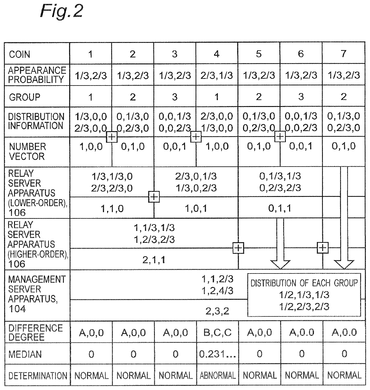
[0101]The operation of the distributed equipment abnormality detection system 101 according to the present embodiment will be described using a simple example in a manner similar to that of the first embodiment. The equipment 102 is a coin, and there are three coin...

third embodiment

[0118]A third embodiment of the present invention is applied to a case in which the physical amount measured in the equipment 102 is not a finite set in the distributed equipment abnormality detection system 101 according to the first embodiment. In such equipment 102, the physical amount x of the equipment 102 is represented by, for example, a random variable of an integer value, a real value, or a vector value. The random variable may be a physical amount represented by equipment constants such as the mass, length, time, current, temperature, amount of substance, or luminous intensity measured inside the equipment 102, or a combination of these equipment constants. In addition, the physical amount x of the equipment 102 may be one using a communication amount of the equipment 102, an occupancy of an arithmetic unit or a memory, or a transition state inside software. Further, the physical amount x of the equipment 102 may be one replaced with a characteristic amount calculated from...


PUM


Abstract

A distributed equipment abnormality detection system is provided for monitoring physical amounts of equipments of identical type and detecting an abnormality of each equipment. The distributed equipment abnormality detection system includes equipment management apparatuses that manage the equipments; and a management server apparatus for communicating the equipment management apparatuses. Each equipment management apparatus includes a communication unit that communicates with the management server apparatus; a measurement unit that repeatedly measures the physical amount of the equipment; a distribution information generation unit that calculates distribution information from the measured physical amount; a distribution comparison unit that calculates a difference between the distribution information generated by the distribution information generation unit, and integrated distribution information on the entire equipments delivered from the management server apparatus; and an abnormality determination unit that determines whether or not the equipment is abnormal based on the calculated difference.

Description

CROSS REFERENCE TO RELATED APPLICATION[0001]This application is a national phase application of PCT / JP2016 / 068411, filed Jun. 21, 2016, which claims priority to Japanese Patent No. 2015-132636, filed Jul. 1, 2015, the entire content and disclosure of each of which is incorporated by reference into the present application.TECHNICAL FIELD[0002]The present invention relates to a distributed equipment abnormality detection system, that collects physical amount data of a large number of equipments such as equipments each including a sensor, and detects abnormal equipment based on collected physical amount data of the equipments.BACKGROUND ART[0003]In recent years, there is an increasing need for a technique for improving efficiency of management and operation of equipments by disposing a large number of sensors in a distributed manner, and collecting and analyzing information on the large number of sensors by communication. For example, a secondary battery such as a lithium ion battery h...

Claims


Application Information

Patent Timeline
Patent Type & Authority Patents(United States)
IPC IPC(8): G06F17/18G06K9/62G01R31/367G01R31/34G01R31/40G01R31/00G05B19/042G06K9/00
CPCG01R31/34G01R31/367G06K9/00G06K9/6277G01R31/40G06F17/18G01R31/008G05B19/042G05B2219/24136G06F18/2415G06F18/00
Inventor KOBAYASHI, SHOICHIWADA, TOSHIHIROTAKEGAMI, TOMOKI
Owner MITSUBISHI ELECTRIC CORP
Why Eureka
Try Eureka