Strain wave gearing with full separation of two stresses

a strain wave and gearing technology, applied in the direction of gearing, gearing elements, hoisting equipment, etc., can solve the problems of ratcheting (tooth jumping), no rigorous examination has been made into ways to actively separate superimposed bending stress and tensile stress produced in sections at either end of the major axis of the external gear, etc., to avoid superimposed flexion-induced bending stress and improve the transmission torque capacity of the strain wave gearing

Active Publication Date: 2020-09-29
HARMONIC DRIVE SYST IND CO LTD
View PDF31 Cites 2 Cited by
  • Summary
  • Abstract
  • Description
  • Claims
  • Application Information

AI Technical Summary

Benefits of technology

[0010]A main object of the present invention is to provide a strain wave gearing, by which superimposition of bending stress and tensile stress produced in sections at either end of the major axis of an external gear can be avoided substantially and completely, without making the flexing amount of the external gear (the average flexing amount of flexing amount at each location in the tooth trace direction) smaller than the normal flexing amount. Another object of the present invention is to provide a strain wave gearing, which is able to further increase transmission torque capacity thereof by realizing an approximately continuous meshing between an external gear and an internal gear along the tooth trace direction thereof as well as by substantially and completely avoiding superimposition of bending stress and tensile stress produced in sections at either end of the major axis of the external gear.
[0023]According to the present invention, it is possible to avoid superimposed flexion-induced bending stresses and tensile stresses caused by load torque arising at the major-axis locations on the ellipsoidal rim neutral curve of the external gear on an axis-perpendicular cross-section having a deflection coefficient κ=1 (principal cross-section) in the external gear of the strain wave gearing, whereby substantially and completely separating the bending stress and the tensile stresses. Therefore, the transmission torque capacity of a strain wave gearing can be improved, without the need to adopt negative deflection flexing having a deflection coefficient κ<1 in a flat-type strain wave gearing, and without the need to adopt negative deflection flexing having a deflection coefficient κ<1 along the entire tooth profile in a cup-type or top-hat-type strain wave gearing.

Problems solved by technology

The smaller tooth depth poses a risk that ratcheting (tooth jumping) will occur during high load torque.
However, no rigorous examination has been made into ways to actively separate superimposition of bending stress and tensile stress produced in sections at either end of the major axis of the external gear.

Method used


Image

  • Strain wave gearing with full separation of two stresses
  • Strain wave gearing with full separation of two stresses
  • Strain wave gearing with full separation of two stresses

Examples


Embodiment Construction

of Strain Wave Gearing)

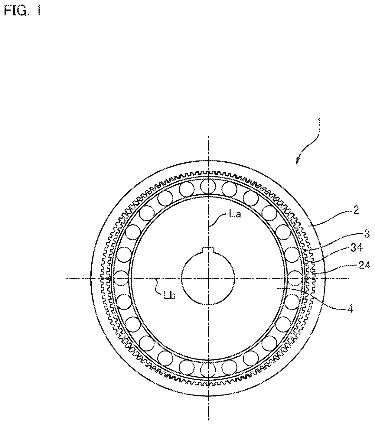
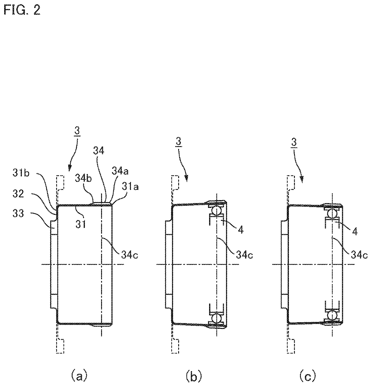
[0040]FIG. 1 is a front view of a strain wave gearing according to the present invention. FIG. 2 (a) to (c) are cross-sectional views showing conditions in which an open-end portion of a flexible external gear in the strain wave gearing is ellipsoidally flexed; FIG. 2 (a) shows a state prior to deformation, FIG. 2 (b) shows a cross-section including the major axis of an ellipsoidal curve subsequent to deformation, and FIG. 2 (c) shows a cross-section including the minor axis of an ellipsoidal curve subsequent to deformation, respectively. In FIGS. 2 (a) to (c), the solid lines represent the diaphragm and boss sections of a flexible external gear having a cup profile, and broken lines represent the diaphragm and boss sections of a flexible external gear having a top hat profile.

[0041]As shown in the drawings, the strain wave gearing 1 has an annular, rigid internal gear 2, a flexible external gear 3 arranged to the inside of the internal gear, and a wave genera...


PUM


Abstract

In a strain wave gearing, the addendum tooth profile of an internal gear is defined by the formula a and that of an external gear is by the formula b at a principal cross-section located at a tooth-trace-direction center of the external gear, on the basis of a movement locus (Mc) of κ=1 by the teeth of the external gear with respect to those of the internal gear. It is possible to avoid superimposition of flexion-induced bending stresses and tensile stresses caused by load torque at the major-axis locations of the external gear, and the transmission torque capacity of a strain wave gearing can be improved.

Description

TECHNICAL FIELD[0001]The present invention relates to a strain wave gearing, in which a flexible external gear is made to flex into an ellipsoidal shape by a wave generator and to partially mesh with a rigid external gear. More specifically, the invention relates to a strain wave gearing for improving the transmission torque capacity thereof by avoiding superimposition of bending stress and tensile stress in sections at either end of the major axis of the ellipsoidal shape of the external gear, in which the bending stress is produced due to flexion and the tensile stress is caused by load torque due to meshing with the internal gear.BACKGROUND ART[0002]A strain wave gearing typically has a rigid internal gear, a flexible external gear coaxially arranged inside the internal gear, and a wave generator fitted into the external gear. A flat-type strain wave gearing is provided with an external gear having external teeth formed on an outer peripheral surface of a flexible cylinder. The e...

Claims


Application Information

Patent Timeline
Patent Type & Authority Patents(United States)
IPC IPC(8): F16H49/00F16H55/08
CPCF16H49/001F16H55/0833F16H2049/003F16H1/32F16H55/08
Inventor ISHIKAWA, SHOICHI
Owner HARMONIC DRIVE SYST IND CO LTD
Why Eureka
Try Eureka