Hand tool comprising vibration damping elements

a technology of vibration damping elements and hand tools, which is applied in the field of hand tools, can solve the problems of limiting the maximum operating time of hand tools per day, affecting the health of workers, and affecting the health of workers, and achieves the effects of small space requirements, high power density, and weight-optimized design

Active Publication Date: 2020-10-06
C & E FEIN GMBH & CO KG
View PDF30 Cites 0 Cited by
  • Summary
  • Abstract
  • Description
  • Claims
  • Application Information

AI Technical Summary

Benefits of technology

[0022]Namely, according to the invention there can be effected a vibrational decoupling between the outer housing and the inner housing at substantially low effort, using simply designed parts. The damping element or the damping elements in the non-mounted state may have a substantially flat design, such as in the shape of a prismatic plate. The non-mounted state of the damping element may correlate with a non-loaded, released position. The plate-shaped damping element now during the assembly of the hand tool may be deformed in a suitable way for providing the peripheral section and the axial section, whereby in a defined way radial and axial forces between the outer housing and the inner housing may be received and transmitted.
[0055]According to a further development in addition at the outer housing there is received a control unit for controlling the drive unit which is displaced from the fan unit into the direction of the rear end of the outer housing and which in particular is arranged between the fan unit and the support contour for receiving the energy storage device. It is advantageous to support the control unit at the outer housing, since it is thus arranged at the vibrationally decoupled gripping side of the hand tool. This may be advantageous for the life-span of the control unit.

Problems solved by technology

Thus for instance in commercial use there exist so-called maximum exposure doses which may limit the maximum operating time of a hand tool per day.
Long-lasting high frequent vibrations may be detrimental to health.
However an effective implementation comes with various challenges.
A further challenge may be the so-called guiding accuracy.
Since with a vibrationally decoupled design there is no stiff connection between the outer part and the inner part of the housing, the forces exerted by the user may lead to respective deformations between the outer housing and the inner housing.

Method used


Image

  • Hand tool comprising vibration damping elements
  • Hand tool comprising vibration damping elements
  • Hand tool comprising vibration damping elements

Examples


Embodiment Construction

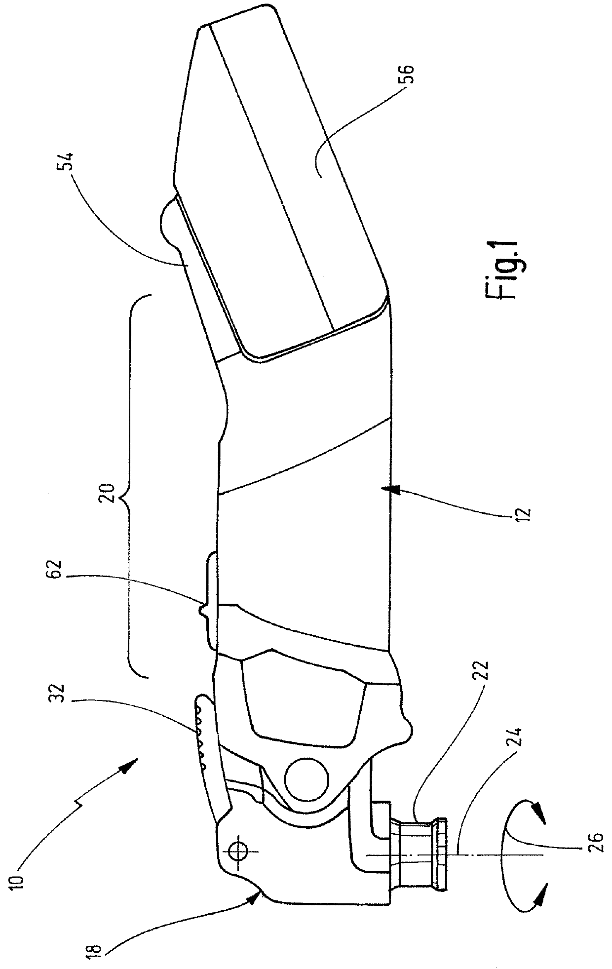
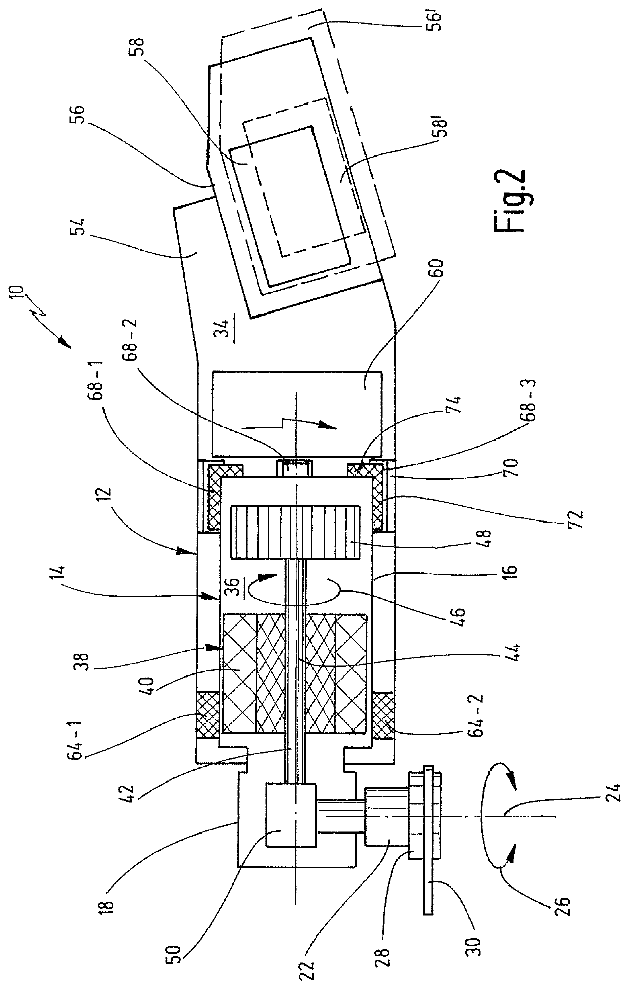
[0069]FIG. 1 shows a side view of a hand tool that is designated in total with 10. FIG. 2 shows a further side view of a hand tool that basically corresponds to the hand tool 10 according to FIG. 1. FIG. 1 generally refers to components of the hand tool 10 that can be seen from the outside. FIG. 2 shows a strongly simplified schematic sectional view for illustrating and explaining inner components of the hand tool 10.

[0070]The hand tool 10 exemplarily is designed as an oscillatory tool. The hand tool 10 comprises an outer housing 12 as well as an inner housing 14 that is at least partially received within the outer housing 12, see in particular FIG. 2. Basically the inner housing 14 may also be designated as a drive housing. The outer housing 12 and the inner housing 14 preferably have a relative distance to each other (in a non-loaded state). In other words it is preferred when at least in the non-loaded state there is no rigid connection or no tight contact, respectively, between ...


PUM


Abstract

A hand tool having a tool spindle that can be driven rotatingly oscillatingly, with an outer housing having a gripping region, an inner housing that is at least partially arranged within the outer housing and coupled therewith, and further having a drive unit including a drive shaft that can be driven rotatingly. The drive unit is received within the inner housing. The drive shaft defines a drive axis. The outer and the inner housings are coupled with each other by a deformable damping element, which in the non-mounted state is formed plate-shaped. The damping element in a mounted state defines a peripheral section and an axial section. The peripheral section in the mounted state is configured for transmitting radial forces between the outer housing and the inner housing. The axial section in the mounted state is configured for transmitting axial forces between the outer housing and the inner housing.

Description

CROSSREFERENCES TO RELATED APPLICATIONS[0001]This application is a continuation of international patent application PCT / EP2015 / 055144, filed on Mar. 12, 2015 designating the U.S.A., which international patent application has been published in German language and claims priority from German patent application 10 2014 103 856.8, filed on Mar. 20, 2014. The entire contents of these priority applications are incorporated herein by reference.BACKGROUND OF THE INVENTION[0002]The invention relates to a hand tool, in particular a hand tool comprising a tool spindle that can be driven rotatingly oscillatingly, comprising an inner housing that at least partially is received within an outer housing and coupled therewith vibration muted, wherein in the inner housing there is received a drive unit comprising a drive spindle that can be driven rotatingly.[0003]Such a hand tool is known from DE 10 2012 103 587 A1. The known hand tool comprises an outer housing extending substantially along a longi...

Claims


Application Information

Patent Timeline
Patent Type & Authority Patents(United States)
IPC IPC(8): B25F5/00B25F5/02
CPCB25F5/001B25F5/02B25F5/006
Inventor SIMMA, TOBIAS
Owner C & E FEIN GMBH & CO KG
Why Eureka
Try Eureka