Method of determining a personalized head-related transfer function and interaural time difference function, and computer program product for performing same

a transfer function and function technology, applied in the field of 3d sound technology, can solve the problems of large errors, not widely used, and the problem of 3d-audio is much more sever

Active Publication Date: 2020-10-06
UNIVERSITY OF ANTWERP
View PDF25 Cites 0 Cited by
  • Summary
  • Abstract
  • Description
  • Claims
  • Application Information

AI Technical Summary

Benefits of technology

[0278]It is an advantage of the present invention that potential inaccuracy of the orientation sensor unit may be addressed by not only relying on the orientation information obtained from the orientation sensor, but by also taking into account the audio signals when determining the head orientation, as will be explained in more detail further below, when describing the algorithm.
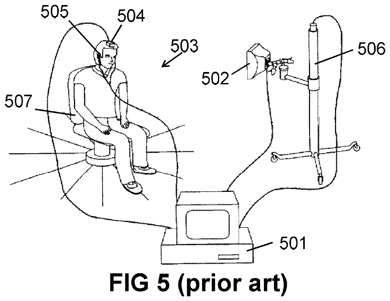
[0279]It is an advantage that the head movements are performed by the person himself, in a way which is much more free and convenient than in the prior art shown in FIG. 5. Moreover, in some embodiments of the invention, the person is not hindered by cables running from the in-ear microphones to the external computer.
[0280]An important difference between the present invention and the co-pending application PCT / EP2016 / 053020 from the same inventors is that, in the former application, the inventors were of the opinion that the orientation unit was not sufficiently accurate for providing reliable orientation data. It is true that the momentary orientation data provided by envisioned orientation sensors is sometimes inaccurate in the sense that hysteresis or “hick-ups” occur, and that the magnetic field sensing is not equally sensitive in all orientations and environments. An underlying idea of the former application was that spatial cues from the captured audio data could help improve the accuracy of the orientation data, which spatial cues can be extracted using a “general” ITDF and / or HRTF function, which in turn was a reason for iterating the algorithm once a “first version” of the personalized ITDF and personalized HRTF was found, because the calculations could then be repeated using the personalized ITDF and / or personalized HRTF yielding more accurate results.
[0282](1) that the use of spatial cues to improve the accuracy of, or to correct the raw orientation data obtained from the orientation unit is not required, and thus also the use of a predefined ITDF (e.g. a general ITDF) and / or a predefined HTRF (e.g. a general HRTF) for extracting those spatial cues is not required; and
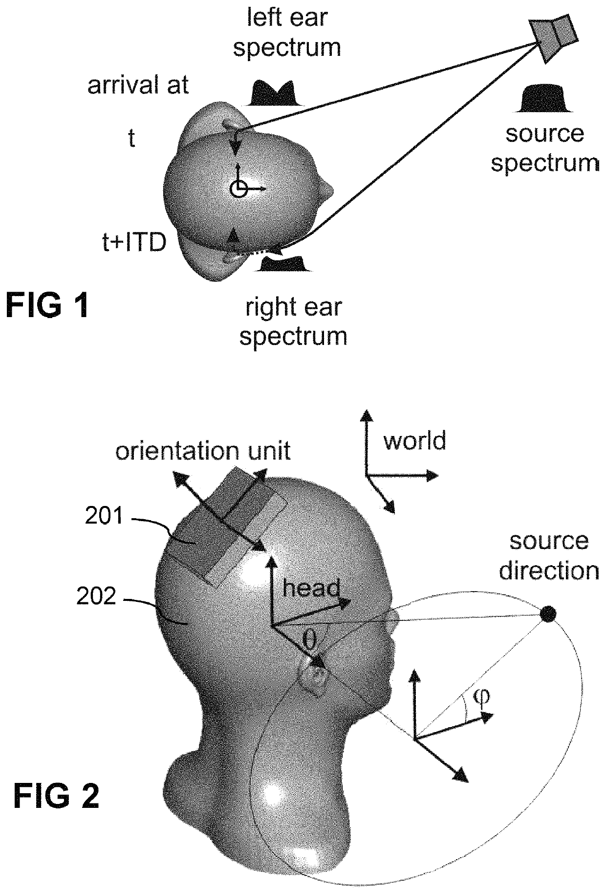
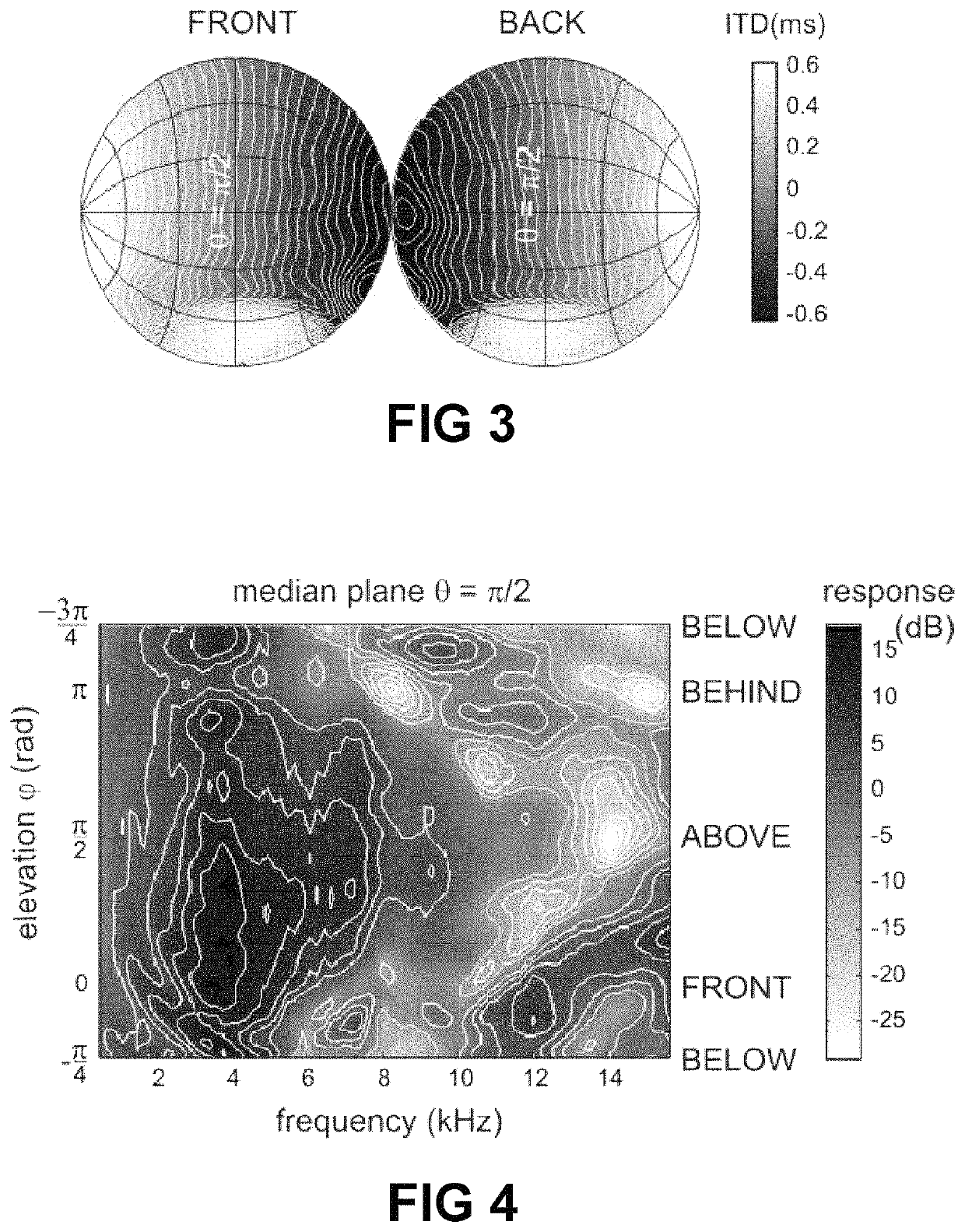
[0283](2) that the joint estimate of the source direction (re world) and the transformation mapping the smartphone reference frame to the head reference frame can be split into two simpler estimation problems performed consecutively. This allows reformulation of the search problem from one performed in a 5 dimensional search space (2 angles to specify source direction +3 angles to specify smartphone-head transformation) into two simpler problems, first solving a problem in a 2 dimensional search space (2 angles to specify source direction) and using those results subsequently solving a problem in a 3 dimensional search space (3 angles to specify smartphone-head transformation). This approach is made possible by the fact that the measured / calculated ITD and / or spectral information when assigned to an incorrect source direction, gives rise to a completely distorted “image” of the ITDF and HRTF when mapped on the sphere, with many high order components, very unlike the relatively continuous or relatively smooth drawings shown in FIG. 3 and FIG. 4. The present invention takes advantage of that insight, by using the “smoothness” of the mapped ITDF and / or HRTF as a quality criterion to first find the source direction relative to the world. The exact details of the algorithm will be described further, but the use of such a quality criterion is one of the underlying ideas of the present invention. Stated in simple terms, it boils down to finding the source direction for which the mapped ITDF and / or HRTF on a sphere “look smoother” than for all other possible source directions. It is noted that other quality criteria based on other specific properties of the ITDF and / or HRTF could also be used, e.g. symmetry (except for sign) of ITDF relative to sagittal plane, cylinder symmetry of ITDF around the ear-ear axis. Given the source direction (re world), finding the smartphone-head transformation then reduces to a search problem in a 3-dimensional search space. This 3-dimensional search can be subdivided further by first determining the ear-ear axis (re smartphone) and finally determining the rotation angle around the ear-ear axis.
[0284]An important advantage of this insight, namely that “smoothness of the mapped ITDF and / or mapped HRTF” can be used as a quality criterion to find the (most likely) source direction, is an important insight, inter alia because (1) it allows that the ITDF and HRTF of a particular person can be determined without using the ITDF and HRTF of other people (or a general ITDF and / or general HRTF), and (2) because it offers huge advantages in terms of computational complexity and computation time. To give an idea, using a method according to the present invention, the calculations required to determine the ITDF and HRTF on a standard laptop computer with e.g. a 2.6 GHz processor (anno 2016) using non-optimal code, only takes about 15 minutes, even without attempts to optimize the code.

Problems solved by technology

Currently, there are already a lot of applications on the market that use the HRTF to create a virtual 3D impression, but so far they are not widely used.
When for an individual, the distance between the eyes is significantly different from the average distance, it may occur that the users depth perception is not optimal, causing the feeling that “something is wrong”, but the problems related to 3D-audio are much more severe.
Small differences may cause large errors.
Equipped with virtual “average ears”, the user experiences effectively a spatial effect—the sound is no longer inside the head-, but somewhere outside the head, but there is often much confusion about the direction where the sound is coming from.
Most mistakes are made in the perception of the elevation, but also, and this is much more disturbing: front and rear are often interchanged.
Sound that should actually come from the front, is perceived as coming from behind, significantly lowering the usefulness of this technology.
Hence, despite the fact that the HRTF and ITDF of different people are similar, even small differences between a person's true HRTF and ITDF and the general HRTF and ITDF cause errors which, in contrast to 3D-vision, are detrimental to the spatial experience.
Although in recent years progress has been made and new methods have been developed to simplify this procedure, such measurements remain very cumbersome and expensive.
It is therefore not possible to measure the HRTF and ITDF of all potential users in this way.

Method used


Image

  • Method of determining a personalized head-related transfer function and interaural time difference function, and computer program product for performing same
  • Method of determining a personalized head-related transfer function and interaural time difference function, and computer program product for performing same
  • Method of determining a personalized head-related transfer function and interaural time difference function, and computer program product for performing same

Examples


first embodiment

[0320]FIG. 10 is a flow-chart representation of a method 1000 according to the present invention. For illustrative purposes, in order not to overload FIG. 10 and FIG. 11 with a large amount of arrows, this flow-chart should be interpreted as a sequence of steps 1001 to 1005, step 1004 being optional, with optional iterations or repetitions (right upwards arrow), but although not explicitly shown, the data provided to a “previous” step is also available to a subsequent step. For example the orientation sensor data is shown as input to block 1001, but is also available for block 1002, 1003, etc. Likewise, the output of block 1001 is not only available to block 1002, but also to block 1003, etc.

[0321]In step 1001 the smartphone orientation relative to the world (for example expressed in 3 Euler angles) is estimated for each audio fragment. An example of this step is shown in more detail in FIG. 13. This step may optionally take into account binaural audio data to improve the orientatio...

embodiment 1000

[0326]An example of this embodiment 1000 will be described in the Appendix.

[0327]The inventors are of the opinion that both the particular sequence of steps (for obtaining the sound direction relative to the head without actually imposing it or measuring it but in contrast using a smartphone which can moreover be oriented in any arbitrary orientation), as well as the specific solution proposed for step 1002 are not trivial.

second embodiment

[0328]FIG. 11 is a variant of FIG. 10 and shows a method 1100 according to the present invention. The main difference between the method 1100 of FIG. 11 and the method 1000 of FIG. 10 is that step 1102 may also take into account a priori information of the smartphone position / orientation, if that is known. This may allow to estimate the sign of the source already in step 1102.

[0329]Everything else which was mentioned in FIG. 10 is also applicable here.

[0330]FIG. 12 shows a method 1200 (i.e. a combination of steps) which can be used to estimate smartphone orientations relative to the world, based on orientation sensor data and binaural audio data, as can be used in step 1001 of the method of FIG. 10, and / or in step 1101 of the method of FIG. 11.

[0331]In step 1201 sensor data is obtained or readout or otherwise obtained from one or more sensors of the orientation unit, for example data from a magnetometer and / or data from an accelerometer and / or data from a gyroscope, and preferably a...


PUM


Abstract

A method of estimating an individualized head-related transfer function and an individualized interaural time difference function of a particular person, comprises the steps of: a) obtaining a plurality of data sets comprising a left and a right audio sample from in-ear microphones, and orientation information from an orientation unit, measured in a test-arrangement where an acoustic test signal is rendered via a loudspeaker and the person is moving the head; b) extracting interaural time difference values and / or spectral values, and corresponding orientation values; c) estimating a direction of the loudspeaker relative to the head using a predefined quality criterion; d) estimating an orientation of the orientation unit relative to the head; e) estimating the individualized ITDF and the individualized HRTF. A computer program product may be provided for performing the method, and a data carrier may contain the computer program.

Description

FIELD OF THE INVENTION[0001]The present invention relates to the field of 3D sound technology. More particularly, the present invention relates to a computer-implemented method of estimating an individualized head-related transfer function (HRTF) and an individualized interaural time difference function (ITDF) of a particular person. The present invention also relates to a computer-program product and a data carrier comprising such computer program product, and to a kit of parts comprising such data carrier.BACKGROUND OF THE INVENTION[0002]Over the past decades there has been great progress in the field of virtual reality technology, in particular with regards to visual virtual reality. 3D TV screens have found their way to the general public, and especially the home theaters and video games take advantage hereof. But 3D sound technology still lags behind. Yet, it is—at least in theory—quite easy to create a virtual 3D acoustic environment, called Virtual Auditory Space (VAS). When ...

Claims


Application Information

Patent Timeline
Patent Type & Authority Patents(United States)
IPC IPC(8): H04S7/00H04R5/027H04R3/04H04R5/033H04R5/04H04R5/02
CPCH04R5/02H04R5/027H04R3/04H04R5/04H04S7/303H04R5/033H04S2400/15H04S2420/01H04S7/304H04R2430/20
Inventor REIJNIERS, JONASPEREMANS, HERBERTPARTOENS, BART WILFRIED M
Owner UNIVERSITY OF ANTWERP
Why Eureka
Try Eureka