Omni directional turntable assembly

a turntable and assembly technology, applied in the field of cargo loading, can solve problems such as delay in the loading process of uld

Active Publication Date: 2020-10-13
GOODRICH CORP OF CHARLOTTE
View PDF53 Cites 4 Cited by
  • Summary
  • Abstract
  • Description
  • Claims
  • Application Information

AI Technical Summary

Benefits of technology

[0012]In addition to one or more of the features described above, or as an alternative, further embodiments may include: a wear cover configured to protect the omni wheel from impacts in a direction about perpendicular to a direction of a tangential angular velocity vector of the omni wheel.

Problems solved by technology

This process to change the direction of the ULD ultimately delays the loading process of ULD.

Method used


Image

  • Omni directional turntable assembly
  • Omni directional turntable assembly
  • Omni directional turntable assembly

Examples


Embodiment Construction

[0034]A detailed description of one or more embodiments of the disclosed apparatus and method are presented herein by way of exemplification and not limitation with reference to the Figures.

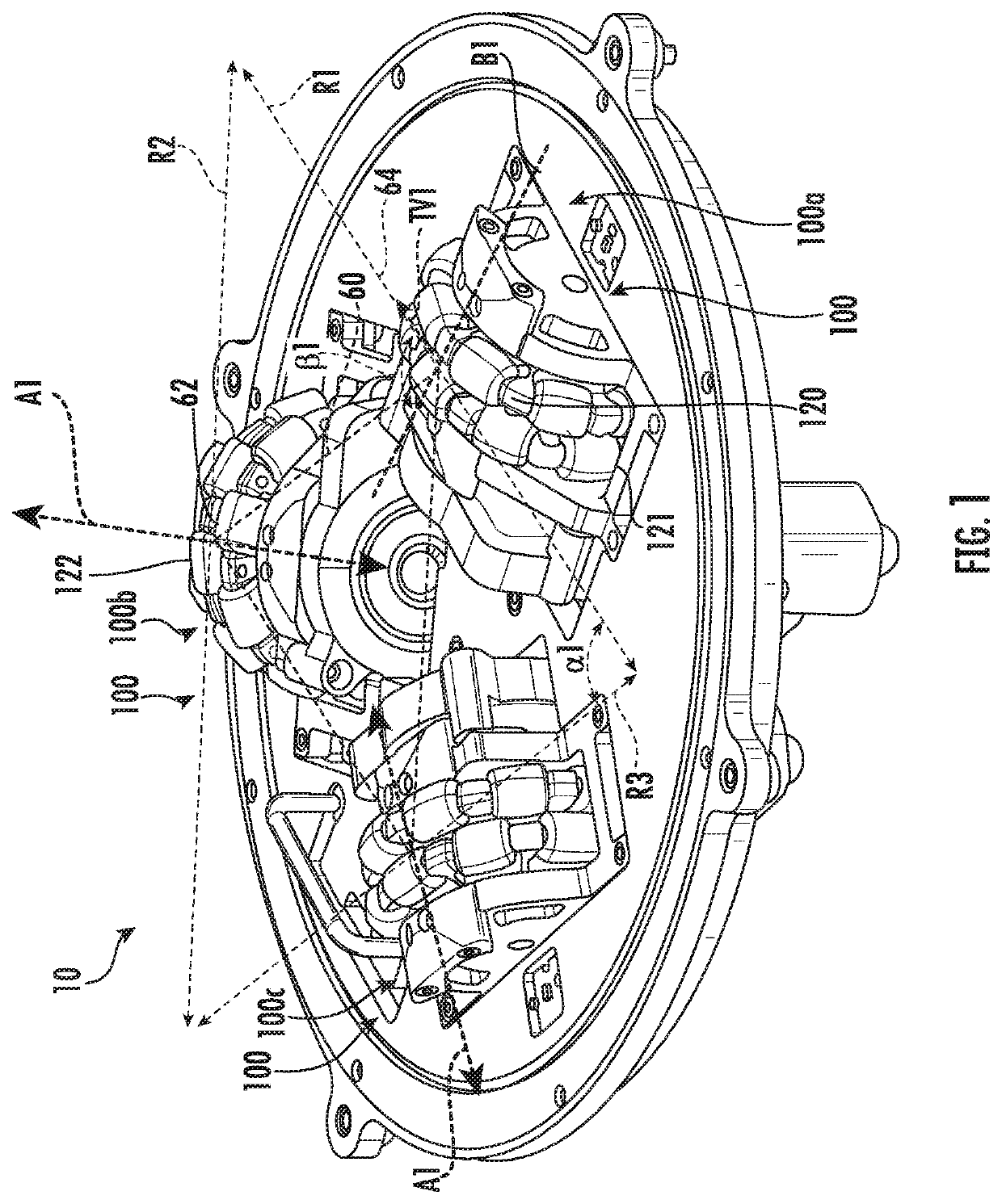
[0035]Referring to FIG. 1, an isometric view of a turntable assembly 10 is illustrated, in accordance with an embodiment of the present disclosure. The turntable assembly 10 includes three omni-directional wheel assemblies 100. Each of the three omni-directional wheel assemblies 100 may be referred to and identified individually as a first omni-directional wheel assembly 100a, a second omni-directional wheel assembly 100a, and a third omni-directional wheel assembly 100b. In an embodiment, the three omni-directional wheel assemblies 100 may be oriented in a triangular orientation relative to each other, as shown in FIG. 1. In the triangular orientation, each omni-directional wheel assembly 100 may be located at a corner 62 of a triangle 60 of the triangular orientation. In an embodiment, the tria...


PUM


Abstract

A turntable assembly for a cargo bay floor including: three omni-directional wheel assemblies oriented in a triangular orientation forming a triangle with one of the three omni-directional wheel assemblies at each corner of the triangle, wherein each of the three omni-directional wheel assemblies include: an omni wheel; and a motor operably connected to the omni wheel, the motor being configured to rotate the omni wheel.

Description

CROSS-REFERENCE TO RELATED APPLICATIONS[0001]This application claims the benefit of Provisional Indian Application No. 201811030856 filed Aug. 17, 2018, which is incorporated herein by reference in its entirety.BACKGROUND[0002]The subject matter disclosed herein generally relates to the cargo loading, and more particularly to an apparatus and method for loading cargo.[0003]Conventional cargo bay floors typically incorporate freight common turntables (FCT) that utilize driving rollers that drive unit load devices (ULD) along the FCT within an aircraft cargo bay by actively rotating wheels of the driving rollers to move and transfer ULD from one driving roller to another. In order to change the direction of the ULD the driving roller must drop below the FCT and rotate to the desired direction of motion. Once the desired direction of motion is achieved then the driving roller may rise back up above the FCT and move the ULD. This process to change the direction of the ULD ultimately del...

Claims


Application Information

Patent Timeline
Patent Type & Authority Patents(United States)
IPC IPC(8): B64D9/00B65G35/06B65G43/00B60B19/00
CPCB65G35/06B65G43/00B60B19/003B64D9/00B60Y2200/62B65G2203/0283B60B2900/212B65G2812/14B64D2009/006B65G2207/48B60B2900/331B65G39/02B65G67/20B65G2207/34
Inventor PUTHIYAVEETTIL, SAYOOJ ADAVALATHPILLAI JAYA, UNNIKRISHNAN VIJAYAN
Owner GOODRICH CORP OF CHARLOTTE
Why Eureka
Try Eureka