Method for manufacturing of urinary catheters

a manufacturing method and technology for urinary catheters, applied in the field of catheters, can solve the problems of reducing affecting the quality of the catheter, so as to achieve the effect of increasing the volume of the molding cavity

Active Publication Date: 2020-10-20
COLOPLAST AS
View PDF31 Cites 6 Cited by
  • Summary
  • Abstract
  • Description
  • Claims
  • Application Information

AI Technical Summary

Benefits of technology

[0010]Accordingly, the present invention preferably seeks to mitigate, alleviate or eliminate one or more of the above-identified deficiencies in the art and disadvantages singly or in any combination and solves at least the above mentioned problems by providing a method for manufacturing an elongated element, comprising the steps of arranging a molding cavity, defined by a mold a mold insert, said mold insert comprising a mold core and a displaceable mold cavity wall, said displaceable mold cavity wall being arranged between the mold and the mold core, such that the molding cavity has a start volume in a start position of the displaceable mold cavity wall; injecting a liquid material into a proximal end of the molding cavity; displacing the displaceable mold cavity wall, in relation to and along with the mold and the mold core, distally during said injection, to increase the molding cavity volume from the start volume into an end volume at an end position of the displaceable mold cavity wall, wherein the molding cavity in said end position of said displaceable mold cavity wall corresponds to the elongated element; solidifying said liquid material, such that the elongated element is formed; removing said elongated element and mold insert from said mold; and removing said elongated element from said mold insert.

Problems solved by technology

The use of permanent or long-term catheters is usually linked to an individual's hospital stay or at least where the individual is under regular observation of medical professionals, as permanent catheters are not well adapted for self catheterization since they are usually very flexible and have a larger diameter than intermittent catheters.
Injection molding of urinary catheters is however accompanied with several obstacles.
Due to the delicate dimensions of a urinary catheter, such as small tube diameter and wall thickness while being relatively long, also the mold insert / core, forming the lumen of the tubular portion, needs to be thin and long.
When the molten plastic material enters the molding cavity, often under high pressure, the plastic material will whirl in the cavity.
This renders the separation of the molded catheter and the insert / core almost impossible, naturally resulting in useless manufacturing in an industrial scale.
Additionally, even though the stabilization of the insert / core helps the formation of a tubular wall with unitary dimensions, it may be very difficult to separate the insert / core from the molded catheter, due to the large contact surface between the insert / core and the plastic material.
This problem is specifically significant when the injected material is a plastic material with high adherence properties, which is often the case with plastic materials with well-suited flexibility properties for the intended purpose.

Method used


Image

  • Method for manufacturing of urinary catheters
  • Method for manufacturing of urinary catheters
  • Method for manufacturing of urinary catheters

Examples


Embodiment Construction

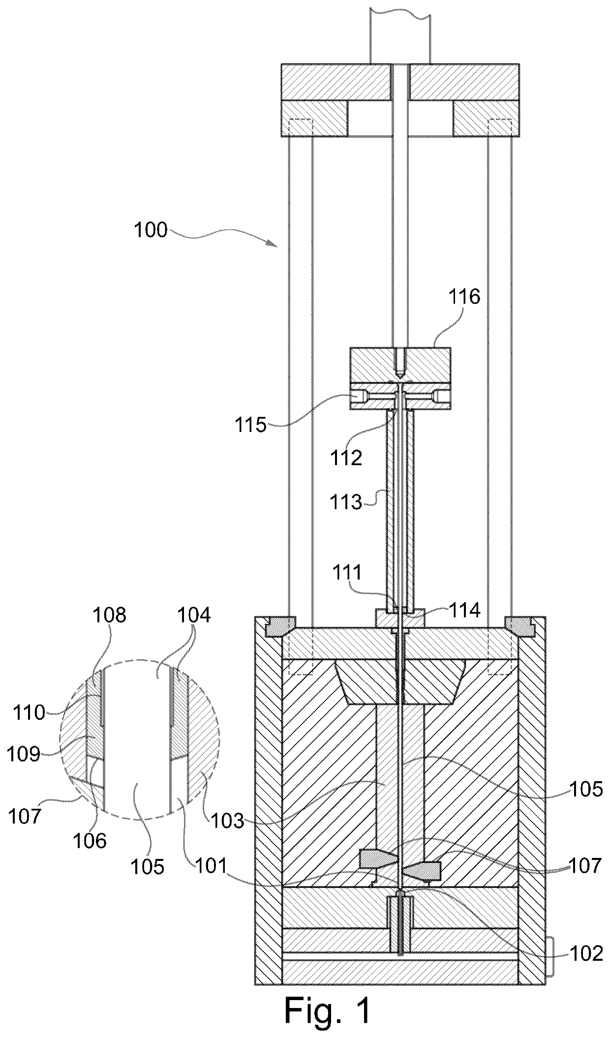
[0022]The following description focuses on an embodiment of the present invention applicable to an elongated element, and in particular to a urinary catheter, and more specifically an intermittent urinary catheter. However, it will be appreciated that the invention is not limited to this application but may be applied to many other elongated elements, such as Foley catheters or test tubes, etc.

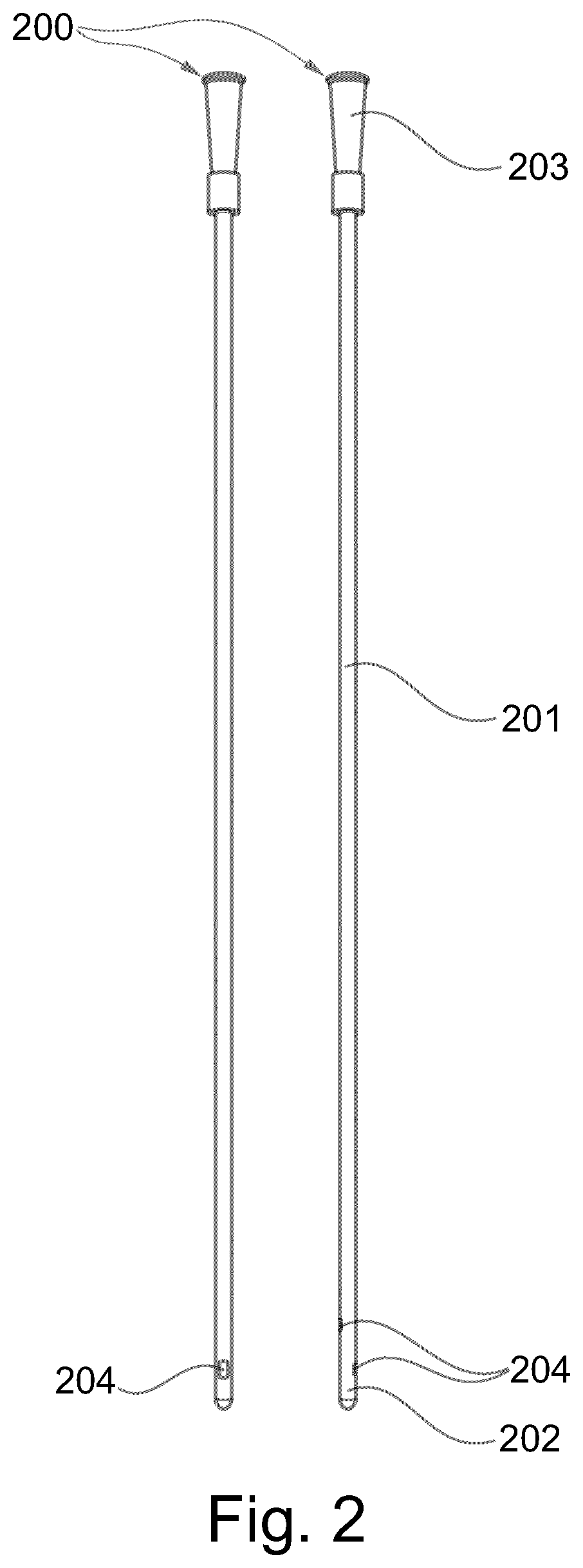
[0023]In specific alternative embodiments, the elongated element according to the present invention may for examples be tubes with snap or friction couplings at both ends, balloon catheters, containers, syringes, pipettes, or test tubes. With regard to tubes with snap or friction couplings at both ends, these may be realized with a male coupling at one end and a female coupling in the other end, such that a multitude of such tubes may be interconnected in series, while maintaining a through channel through the interconnected series of tubes. In this way a series of tubes can be assembled to de...


PUM

PropertyMeasurementUnit
lengthaaaaaaaaaa
lengthaaaaaaaaaa
angleaaaaaaaaaa

Abstract

A method for manufacturing an elongated element (200) is provided. The method comprises arranging a molding cavity (101), defined by a mold (103) and a mold insert (104), said mold insert (104) comprising a mold core (105) and a displaceable mold cavity wall (106), said displaceable mold cavity wall (106) being arranged between the mold (103) and the mold core (105), such that the molding cavity has a start volume in a start position of the displaceable mold cavity wall (106). Then a liquid material is injected into a proximal end (102) of the molding cavity (101), where after the displaceable mold cavity wall (106) is displaced in relation to and along with the mold (103) and the mold core (105), distally during said injection, to increase the molding cavity volume from the start volume into an end volume at an end position of the displaceable mold cavity wall (106), wherein the molding cavity (101) in said end position of the displaceable mold cavity wall (106) corresponds to the elongated element (200). The liquid material is solidified, such that the elongated element (200) is formed, and the elongated element (200) and mold insert (104) is removed from said mold (103), where after the elongated element (200) is removed from said mold insert (104). An elongated element and a mold assembly for the manufacture thereof are also provided.

Description

[0001]This application is a National Stage Application of PCT / EP2013 / 053676, filed 25 Feb. 2013, which claims benefit of Serial No. PA2012 00156, filed 27 Feb. 2012 in Denmark and Serial No. PA2013 000061, filed 31 Jan. 2013 in Denmark and which applications are incorporated herein by reference. To the extent appropriate, a claim of priority is made to each of the above disclosed applications.FIELD OF THE INVENTION[0002]This invention pertains in general to the field of injection molding of thin-walled, elongated, elements, with a tubular body and an optionally substantially closed end. More particularly the invention relates to a catheter, such as a urinary catheter, with an elongated tubular portion and a tip portion. Furthermore, the present invention pertains to a method of manufacturing such elements and catheters, and an assembly for forming a molding cavity.BACKGROUND OF THE INVENTION[0003]Urinary catheters are widely used by persons who have problems with respect to unintent...

Claims


Application Information

Patent Timeline
Patent Type & Authority Patents(United States)
IPC IPC(8): B29C45/26B29C45/56B29C45/43A61M25/00A61M39/10B29C45/80B29C45/00B29L23/00B29L31/00
CPCA61M25/0017B29C45/261B29C45/0046B29C45/80A61M39/10A61M25/0009B29C45/2628B29C45/43B29C45/56B29L2023/001B29C2045/5695A61M2207/10A61M2202/0496B29L2031/7542A61M2202/0014
Inventor ROLSTED, ERIKØELUND, JAKOBSCHERTIGER, LARS OLAVLUTHER, PREBENBAGER, KIM
Owner COLOPLAST AS
Why Eureka
Try Eureka