Laminated cell and method for manufacturing same
a technology of laminated cells and cell parts, which is applied in the field of laminated cells, can solve the problems of difficult improvement in productivity, difficult to achieve the effect of reducing the size of the cell through the reduction of the size of the bag-shaped separator, and large number of work steps. , to achieve the effect of easy reduction in size and excellent productivity
- Summary
- Abstract
- Description
- Claims
- Application Information
AI Technical Summary
Benefits of technology
Problems solved by technology
Method used
Image
Examples
first embodiment
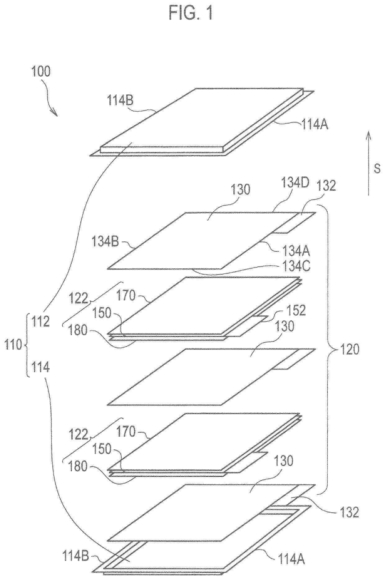
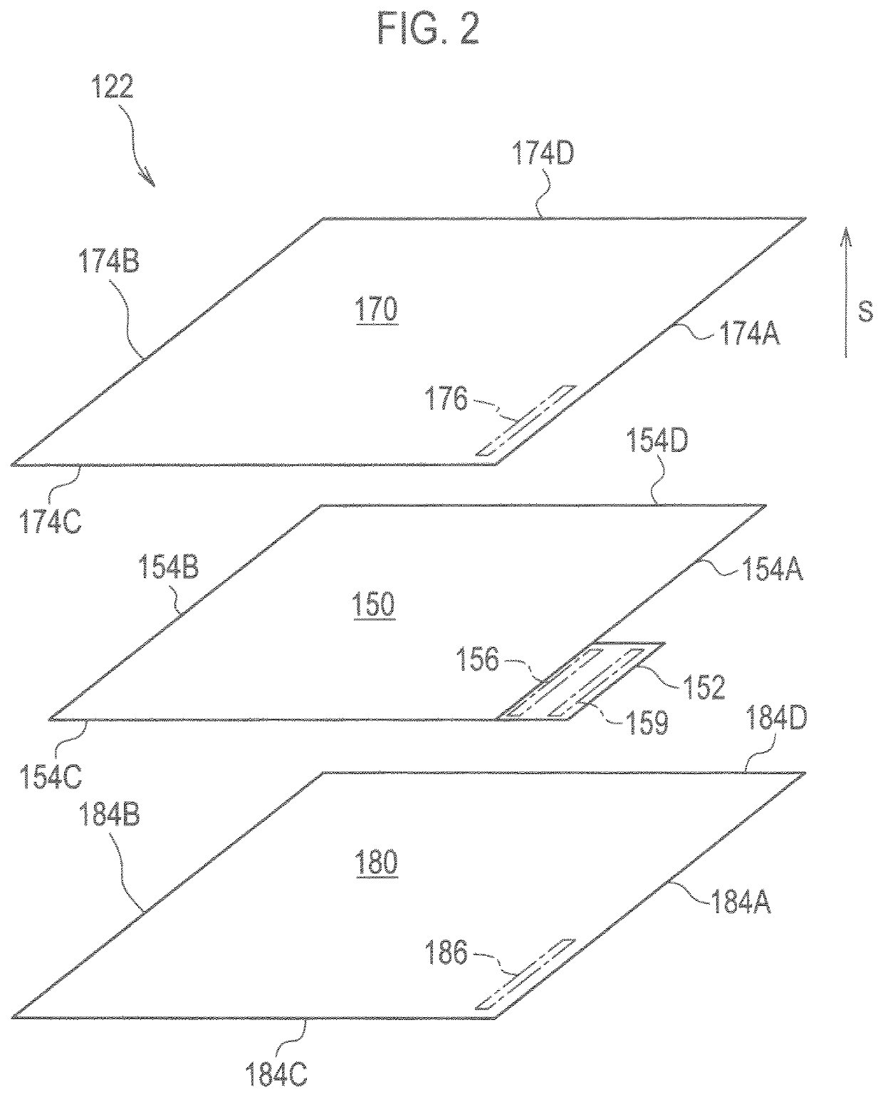
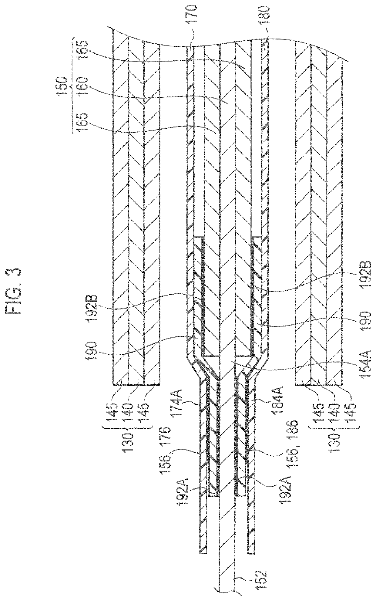
[0035]FIG. 1 is an exploded perspective view for explaining a laminated cell in a first embodiment and FIG. 2 is an exploded perspective view for explaining a sub-assembly shown in FIG. 1. Moreover, FIGS. 3 and 4 are cross-sectional views respectively for explaining a front portion and a rear portion of the sub-assembly shown in FIG. 1.
[0036]A laminated cell 100 in the first embodiment is formed of, for example, a substantially-rectangular lithium-ion secondary cell and has an exterior member 110 and a laminated body 120 forming a cell main body.
[0037]The exterior member 110 is formed of an upper portion 112 and a lower portion 114 and is used to prevent shock from the outside and deterioration due to an environment. Outer peripheral portions of sheet members forming the upper portion 112 and the lower portion 114 are partially or entirely bonded to each other by thermal fusion bonding. From the view point of weight reduction and thermal conductivity, the sheet members in the exteri...
second embodiment
[0069]Next, a laminated cell in a second embodiment is described. FIG. 13 is an exploded perspective view for explaining the laminated cell in the second embodiment and FIG. 14 is exploded perspective view for explaining a sub-assembly shown in FIG. 13. In the following description, the members having the same function as those in the first embodiment are denoted by similar reference numerals and description thereof is omitted to avoid overlapping description.
[0070]The second embodiment generally differs from the first embodiment in configurations of a negative electrode, a positive electrode, and current collecting portions. Specifically, as shown in FIG. 13, a laminated cell 200 in the second embodiment has an exterior member 210 formed of an upper portion 212 and a lower portion 214; and a laminated body 220 forming a cell main body. Note that reference numerals 214A and 214B respectively denote a front edge portion and a rear edge portion of the exterior member 210.
[0071]The lam...
third embodiment
[0083]Next, a laminated cell in a third embodiment is described. FIG. 19 is an exploded perspective view for explaining the laminated in the third embodiment. FIG. 20 is an exploded perspective view for explaining a first sub-assembly shown in FIG. 19. FIG. 21 is a cross-sectional view for explaining a front portion of the first sub-assembly shown in FIG. 20. FIG. 22 is an exploded perspective view for explaining a second sub-assembly shown in FIG. 19. FIG. 23 is a cross-sectional view for explaining a front portion of the second sub-assembly shown in FIG. 22.
[0084]The third embodiment generally differs from the first embodiment in the configuration of the sub-assemblies. Specifically, a laminated cell 300 in the third embodiment has: an exterior member 310 formed of an upper portion 312 and a lower portion 314; and a laminated body 320 forming a cell main body. Note that reference numerals 314A and 314B respectively denote a front edge portion and a rear edge portion of the exterio...
PUM
| Property | Measurement | Unit |
|---|---|---|
| current | aaaaa | aaaaa |
| current | aaaaa | aaaaa |
| current | aaaaa | aaaaa |
Abstract
Description
Claims
Application Information
 - R&D
- Intellectual Property
- Life Sciences
- Materials
- Tech Scout
- Unparalleled Data Quality
- Higher Quality Content
- 60% Fewer Hallucinations
Browse by: Latest US Patents, China's latest patents, Technical Efficacy Thesaurus, Application Domain, Technology Topic, Popular Technical Reports.
© 2025 PatSnap. All rights reserved.Legal|Privacy policy|Modern Slavery Act Transparency Statement|Sitemap|About US| Contact US: help@patsnap.com


