Imaging optical system
a technology of optical system and optical system, applied in the field of imaging optical system, can solve the problems of inability to obtain a sufficiently wide angle of view, inability to reduce the distance between the principal points of the first lens and the second lens, and inability to achieve the effect of high resolution and imaging optical system
- Summary
- Abstract
- Description
- Claims
- Application Information
AI Technical Summary
Benefits of technology
Problems solved by technology
Method used
Image
Examples
example 1
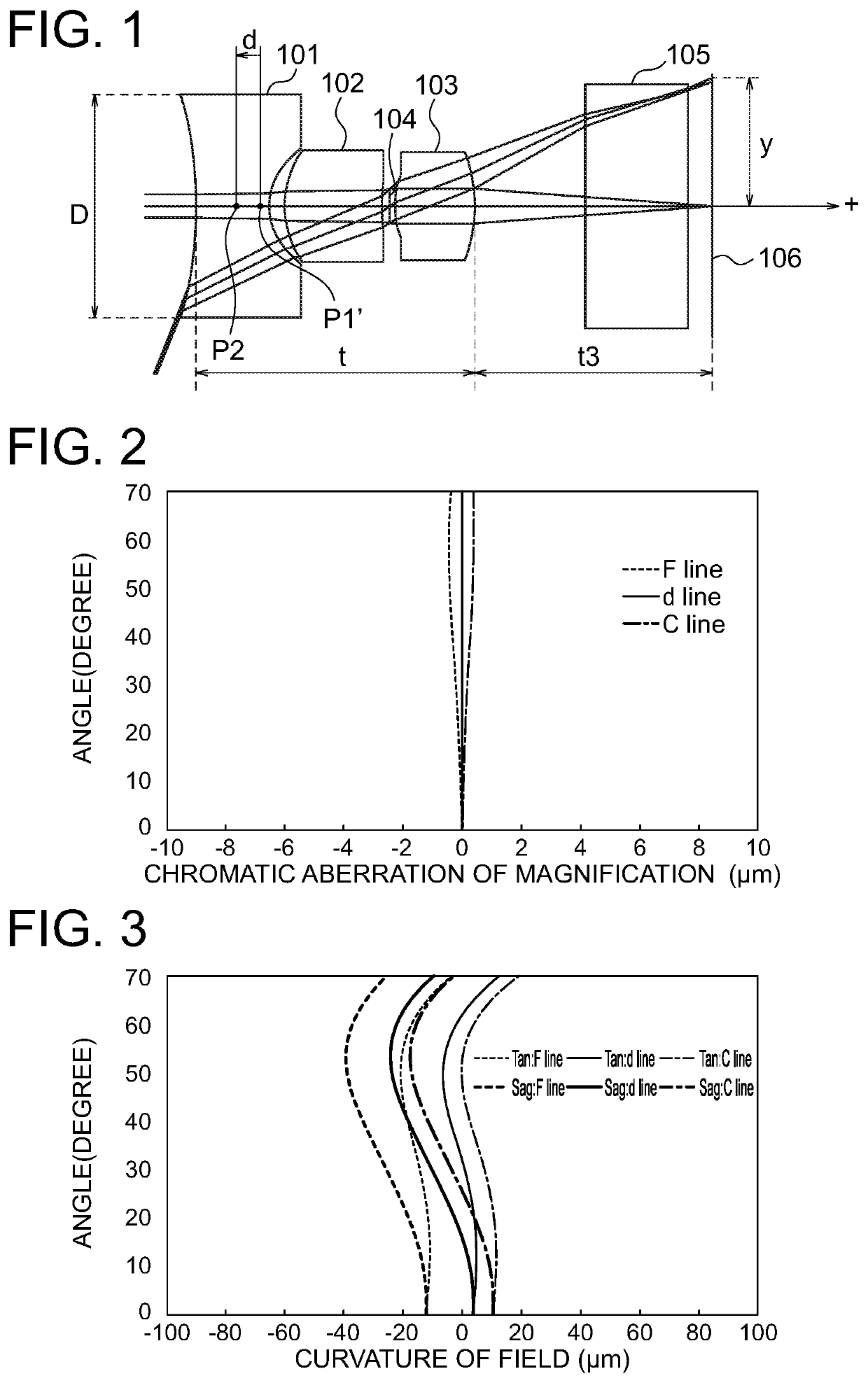
[0092]FIG. 1 shows a layout of the imaging optical system according to Example 1. The imaging optical system includes a first lens 101 having a negative refractive power, a second lens 102 having a positive refractive power, an aperture stop 104 and a third lens 103 having a positive refractive power, which are arranged from the object side to the image side. Light beams that pass through the above-described lenses pass through an optical member 105 and are focused on an image plane 106. The optical member 105 is a cover glass for a sensor or the like. FIG. 1 shows the optical path of a light beam including the principal ray that travels parallel to the optical axis from a surface of the object that is 15 mm distant from the first lens along the optical axis and the optical path of a light beam including the principal ray that travels at the angle of the half value of the angle of view to the optical axis from the surface of the object that is 15 mm distant from the first lens along...
example 2
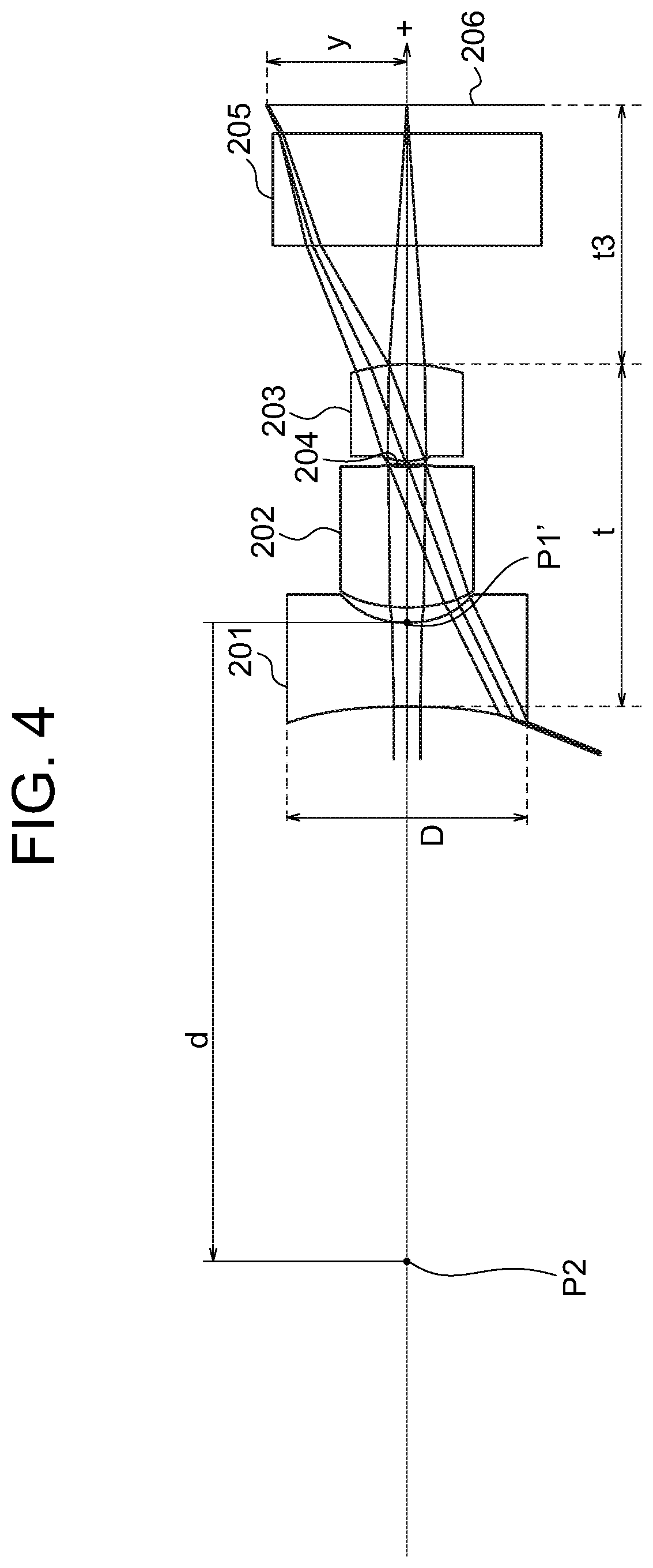
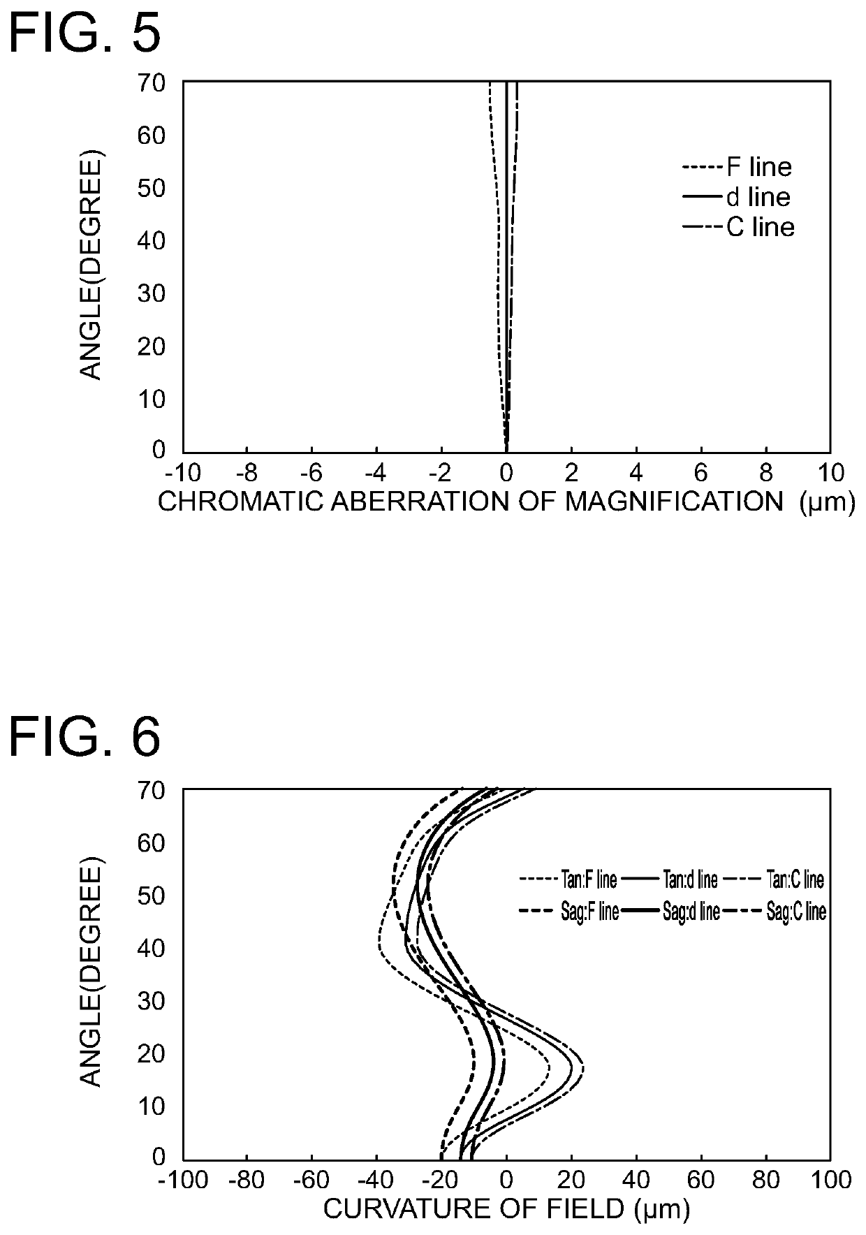
[0100]FIG. 4 shows a layout of the imaging optical system according to Example 2. The imaging optical system includes a first lens 201 having a negative refractive power, a second lens 202 having a positive refractive power, an aperture stop 204 and a third lens 203 having a positive refractive power, which are arranged from the object side to the image side. Light beams that pass through the above-described lenses pass through an optical member 205 and are focused on an image plane 206. The optical member 205 is a cover glass for a sensor or the like. FIG. 4 shows the optical path of a light beam including the principal ray that travels parallel to the optical axis from a surface of the object that is 15 mm distant from the first lens along the optical axis and the optical path of a light beam including the principal ray that travels at the angle of the half value of the angle of view to the optical axis from the surface of the object that is 15 mm distant from the first lens along...
example 3
[0108]FIG. 7 shows a layout of the imaging optical system according to Example 3. The imaging optical system includes a first lens 301 having a negative refractive power, a second lens 302 having a positive refractive power, an aperture stop 304 and a third lens 303 having a positive refractive power, which are arranged from the object side to the image side. Light beams that pass through the above-described lenses pass through an optical member 305 and are focused on an image plane 306. The optical member 305 is a cover glass for a sensor or the like. FIG. 7 shows the optical path of a light beam including the principal ray that travels parallel to the optical axis from a surface of the object that is 15 mm distant from the first lens along the optical axis and the optical path of a light beam including the principal ray that travels at the angle of the half value of the angle of view to the optical axis from the surface of the object that is 15 mm distant from the first lens along...
PUM
 Abstract
Description
Claims
Application Information
 - R&D
- Intellectual Property
- Life Sciences
- Materials
- Tech Scout
- Unparalleled Data Quality
- Higher Quality Content
- 60% Fewer Hallucinations
Browse by: Latest US Patents, China's latest patents, Technical Efficacy Thesaurus, Application Domain, Technology Topic, Popular Technical Reports.
© 2025 PatSnap. All rights reserved.Legal|Privacy policy|Modern Slavery Act Transparency Statement|Sitemap|About US| Contact US: help@patsnap.com


