
Spinal implants

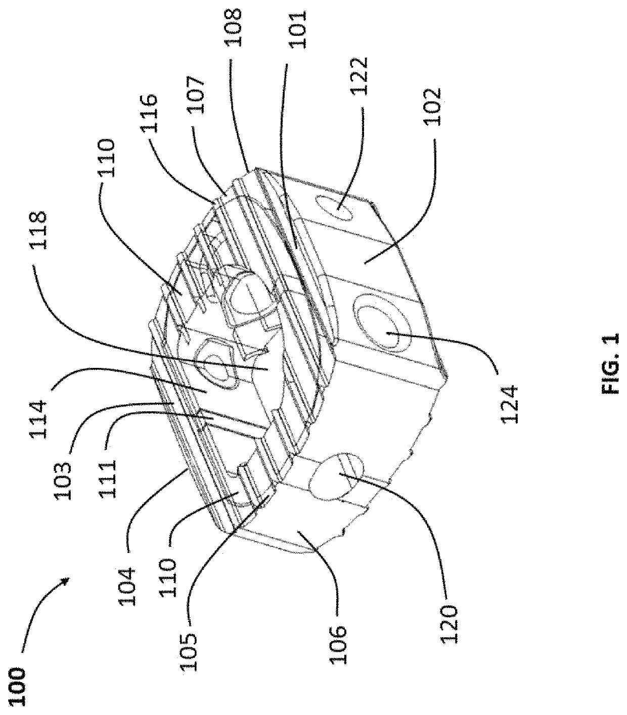
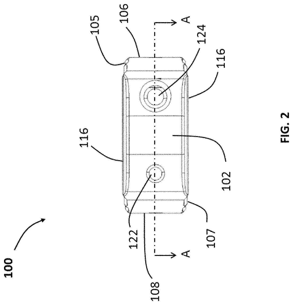
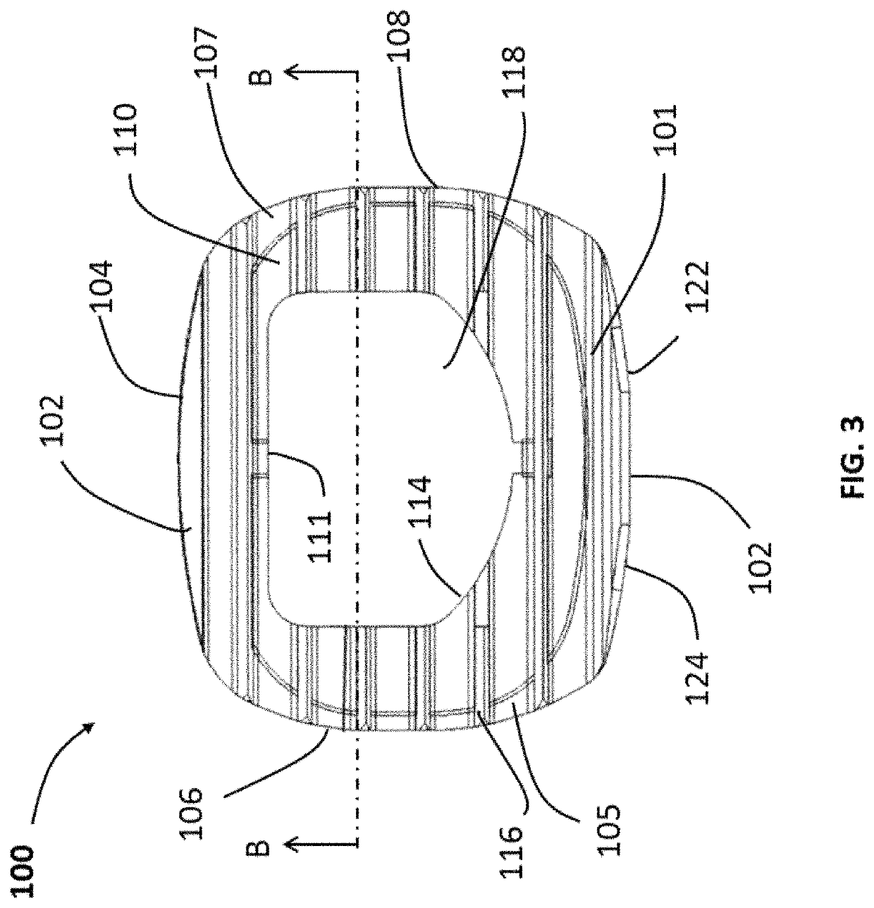
a technology for spinal implants and implants, applied in the field of spinal implants, can solve the problems of degeneration, bulging, herniation, thinning and abnormal movement, and difficult manufacturing of implants, and achieve the effects of reducing the number of existing implants that implement porous materials and reducing the number of existing implants

Active Publication Date: 2020-11-17
STRYKER EURO OPERATIONS HLDG LLC
View PDF478 Cites 11 Cited by
  • Summary
  • Abstract
  • Description
  • Claims
  • Application Information

AI Technical Summary

Problems solved by technology

Typical disc issues include, inter alia, degeneration, bulging, herniation, thinning and abnormal movement.
Although there is little doubt that the bone growth into the implant is beneficial in maintaining an implant in place, these implants are often very difficult (and thusly, expensive) to manufacture.
Additionally, existing implants that implement porous material do so in a limited manner.
Often times, because of manufacturing or strength concerns or the like, the porous material is limited to a thin layer covering the upper and lower surfaces of the implant, which only allows for a small amount of bone to grow into the implant.

Method used


Image

  • Spinal implants
  • Spinal implants
  • Spinal implants

Examples


Embodiment Construction

[0063]Reference will now be made to the embodiments of the present invention illustrated in the accompanying drawings. Wherever possible, the same or like reference numbers will be used throughout the drawings to refer to the same or like features. It should be noted that the drawings are in simplified form and are not drawn to precise scale. Additionally, the term “a,” as used in the specification, means “at least one.” The terminology includes the words above specifically mentioned, derivatives thereof, and words of similar import.

[0064]In describing preferred embodiments of the disclosure, reference will be made to directional nomenclature used in describing the human body. It is noted that this nomenclature is used only for convenience and that it is not intended to be limiting with respect to the scope of the invention. For example, as used herein, when referring to bones or other parts of the body, the term “anterior” means toward the front of the body and the term “posterior”...


PUM

PropertyMeasurementUnit
medial wall thicknessaaaaaaaaaa
pore diameteraaaaaaaaaa

Abstract

Disclosed herein is a spinal implant with a solid frame and a porous inner layer. The implant may have a cavity defined by the porous inner layer. The solid frame may have one or more ribs extending from a medial wall to a lateral wall. The thickness of the porous layer may vary relative the thickness of the solid frame at various locations. An inserter to place a spinal implant and a method to perform same are also disclosed.

Description

CROSS-REFERENCE TO RELATED APPLICATION[0001]The present application claims the benefit of the filing date of U.S. Provisional Patent Application No. 62 / 560,910, filed on Sep. 20, 2017, the disclosure of which is hereby incorporated by referenceBACKGROUND OF THE INVENTION[0002]The present invention generally relates to spinal implants and a method of fabricating the same, and in particular, relates to a spinal implant with porous and solid structures and the methods for fabricating them.[0003]Back pain can be caused by many different maladies, not the least of which are problems that directly impact the intervertebral discs of the spine. Typical disc issues include, inter alia, degeneration, bulging, herniation, thinning and abnormal movement. One method of treatment of such disc problems that has been widely utilized in the field of spinal surgery is a spinal fusion procedure, whereby an affected disc is removed and the adjacent vertebral bodies are fused together through the use of...

Claims


Application Information

Patent Timeline
Patent Type & Authority Patents(United States)
IPC IPC(8): A61F2/44
CPCA61F2/447A61F2/4455A61F2002/3092A61F2002/30962A61F2002/30985A61F2002/4495A61F2310/00023A61F2002/3093A61F2002/30904A61F2002/30011A61F2002/30593
Inventor MILZ, BRYAN D.ALHEIDT, THOMAS A.CETRANGOL, JESSICASCHULTZ, CHRISTIAN KARLSTEINKE, JASONWILLIS, STEVENCIPOLETTI, ROBERTBUSH, JR., CHARLES L.JUCHNO, BRAD
Owner STRYKER EURO OPERATIONS HLDG LLC
Learn More