Control valve for variable displacement compressor

a variable-discharge compressor and control valve technology, which is applied in the direction of valve operating means/release devices, machines/engines, and positive-discharge liquid engines, etc., can solve the problems of increasing bleeding and rapidly changing operation to maximum-capacity operation, and achieves maximum-capacity operation, rapid change of operation, and increased bleeding

Active Publication Date: 2020-11-17
TGK
View PDF15 Cites 11 Cited by
  • Summary
  • Abstract
  • Description
  • Claims
  • Application Information

AI Technical Summary

Benefits of technology

[0007]The present invention has been made in view of these circumstances, and an object thereof is to provide a control valve suitable for efficiently switching the operation of a compressor.
[0009]According to this embodiment, in a control valve having a bleed flow rate controlled so that a sensed pressure becomes a set pressure during steady control, a minimum amount of bleeding through a bleed passage is provided even while a bleed valve is in a closed state. The control valve thus allows constant internal circulation of refrigerant in a compressor. In addition, at startup of the compressor, the bleed valve is further opened to a fully open state, which increase the bleeding and rapidly changes the operation to maximum capacity operation. This allows efficient switching of the operation condition of the compressor.

Problems solved by technology

In addition, at startup of the compressor, the bleed valve is further opened to a fully open state, which increase the bleeding and rapidly changes the operation to maximum capacity operation.

Method used


Image

  • Control valve for variable displacement compressor
  • Control valve for variable displacement compressor
  • Control valve for variable displacement compressor

Examples


first embodiment

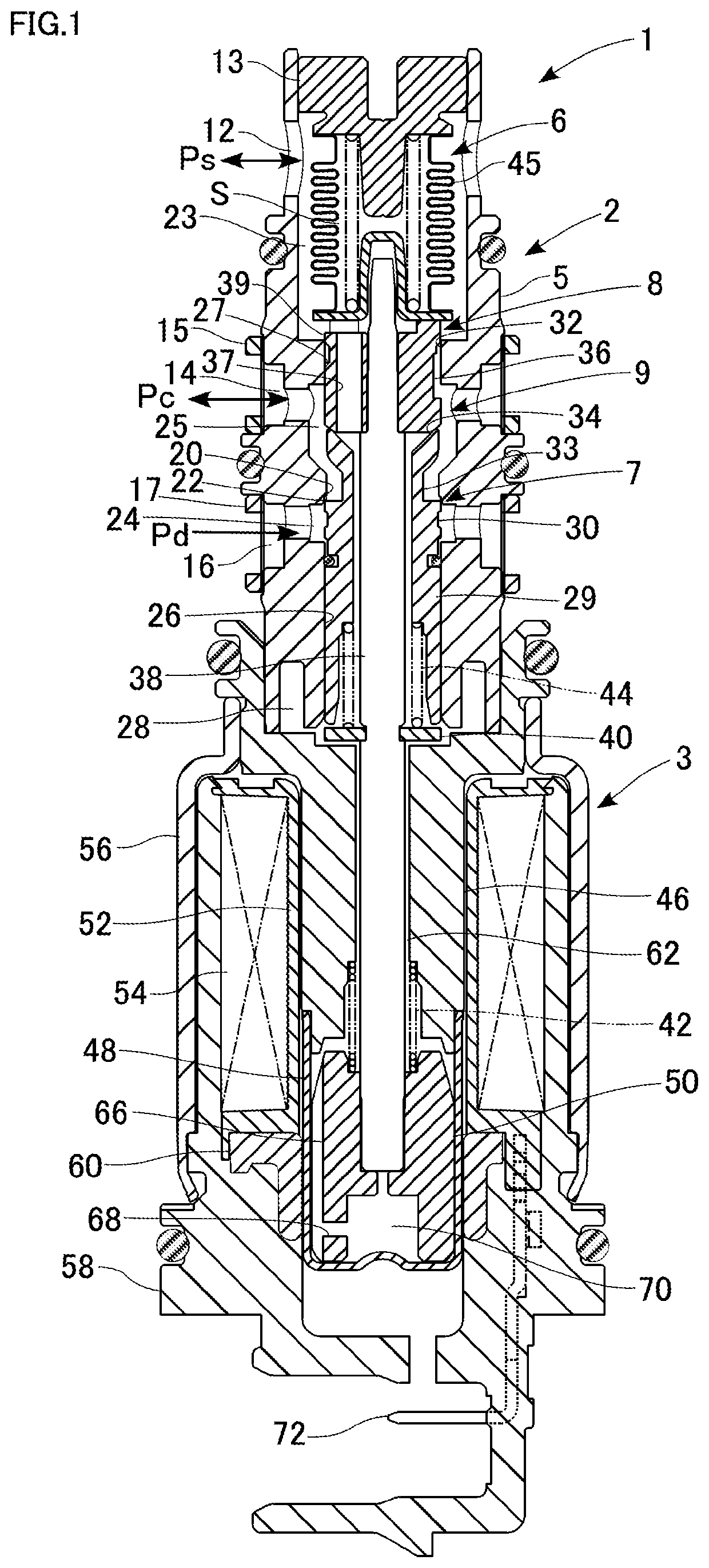
[0024]FIG. 1 is a cross-sectional view illustrating a structure of a control valve according to a first embodiment.

[0025]The control valve 1 controls the discharging capacity of a variable displacement compressor (hereinafter simply referred to as a “compressor”) installed in a refrigeration cycle of an automotive air conditioner. The compressor compresses refrigerant flowing through the refrigeration cycle into a high-temperature and high-pressure gaseous refrigerant, and discharges the compressed gaseous refrigerant. The gaseous refrigerant is condensed by a condenser (external heat exchanger) and then adiabatically expanded by an expander into a low-temperature and low-pressure spray of refrigerant. The low-temperature and low-pressure refrigerant is evaporated by an evaporator, and the air inside the vehicle is cooled by the evaporative latent heat. The refrigerant evaporated by the evaporator is returned to the compressor. In this manner, the refrigerant circulates through the ...

second embodiment

[0080]FIG. 6 is a partially enlarged cross-sectional view of an upper half of a control valve according to a second embodiment. The following description will be focused on differences from the first embodiment.

[0081]A control valve 201 is formed of an integral assembly of a valve unit 202 and a solenoid 203. The valve unit 202 includes a body 205, a power element 6, and so on. The control valve 201 has a structure in which the power element 6, a bleed valve 208, and the solenoid 203 are arranged in this order from one end thereof. The bleed valve 208 functions similarly to the second valve 8 of the first embodiment. In the present embodiment, no valves corresponding to the first valve 7 and the third valve 9 of the first embodiment are provided.

[0082]The body 205 has ports 12 and 14 formed in this order from an upper end thereof. No “discharge chamber communication port is formed. A valve drive member 229 is slidably inserted in a guiding passage 26. An upper part of the valve driv...

third embodiment

[0092]FIG. 9 is a cross-sectional view illustrating a control valve according to a third embodiment. The following description will be focused on differences from the second embodiment.

[0093]A control valve 301 is formed of an integral assembly of a valve unit 302 and a solenoid 303. The valve unit 302 includes a body 305, a power element 6, and so on. A valve seat 331 is formed at an open end of a valve hole 232 on the side of the working chamber 23. A valve element 336 does not have a spool portion 39 as in the second embodiment. The valve element 336 touches and leaves the valve seat 331 to close and open a bleed valve 308. The bleed valve 308 can be fully closed.

[0094]A spring support 340 is provided at a lower end of the body 305. The spring support 340 has a stepped disc-like shape, and is press-fitted into the body 305 in the working chamber 28. An actuating rod 338 extends through the spring support 340. In addition, a spring support 341 is fitted into a middle portion of th...


PUM


Abstract

A control valve includes: a body having a control chamber communication port and a suction chamber communication port; a valve element that moves toward and away from a valve hole to close and opening a bleed valve, the ports communicating with each other through the valve hole; a solenoid to generate a drive force in an opening direction of the bleed valve; and a pressure sensing element to sense a pressure in the suction chamber or a pressure in the control chamber, and generate a counterforce against the drive force from the solenoid depending on a magnitude of the sensed pressure. An opening degree of the bleed valve is controlled so that the sensed pressure becomes a set pressure. A bleed passage for delivering the refrigerant introduced through the control chamber communication port to the suction chamber even while the bleed valve is in a closed state is formed.

Description

CLAIM OF PRIORITY[0001]This application claims priority to Japanese Patent Application No. 2017-076942 filed on Apr. 7, 2017, which is incorporated herein by reference.BACKGROUND OF THE INVENTION1. Field of the Invention[0002]The present invention relates to a control valve for controlling the discharging capacity of a variable displacement compressor.2. Description of the Related Art[0003]An automotive air conditioner generally includes a compressor, a condenser, an expander, an evaporator, and so forth arranged in a refrigeration cycle. The compressor is, for example, a variable displacement compressor (hereinafter also referred to simply as a “compressor”) capable of varying the refrigerant discharging capacity in order to maintain a constant level of cooling capacity irrespective of the engine speed. In this compressor, a piston for compression is linked to a swash plate, which is mounted onto a rotational shaft driven by an engine. The angle of the swash plate is changed to cha...

Claims


Application Information

Patent Timeline
Patent Type & Authority Patents(United States)
IPC IPC(8): F04B27/18F04B49/22
CPCF04B27/1804F04B49/22F04B2027/1868F04B2027/1881F04B2027/1859F04B2027/1813F04B2027/1831F04B39/10F16K31/0603F16K31/0624F04B49/12F04B2205/02F16K31/0613F04B39/08F04B25/04
Inventor TONEGAWA, MASAAKIHAMADA, HIROSHI
Owner TGK
Why Eureka
Try Eureka