
Hydraulic apparatus, in particular hydraulic valve or hydraulic regulator

Active Publication Date: 2020-11-17
LIEBHERR MACHINES BULLE
View PDF22 Cites 0 Cited by
  • Summary
  • Abstract
  • Description
  • Claims
  • Application Information

AI Technical Summary

Benefits of technology

The invention relates to a device for adjusting a screw in a housing. The device has a regulating screw with sliding surfaces that move along different parts of the housing to adjust the screw. The device can apply different torques to the screw depending on the depth of the adjustment. The torque is determined by the friction between the screw and the housing. The device can also have an abutment that limits the depth of the screw. The technical effect of the invention is to provide a device for adjusting a screw that can apply different torques and has a defined screw-in depth.

Problems solved by technology

An exceeding of the upper limit pressure is not possible.
There is, however, a problem with these regulating screws that the user as a rule can only estimate which preload is currently set with difficulty.
Previous regulators neither provide a truly controlled overload range nor do they have technical possibilities to signalize different adjustment ranges to the user at all.

Method used


Image

  • Hydraulic apparatus, in particular hydraulic valve or hydraulic regulator
  • Hydraulic apparatus, in particular hydraulic valve or hydraulic regulator
  • Hydraulic apparatus, in particular hydraulic valve or hydraulic regulator

Examples


Embodiment Construction

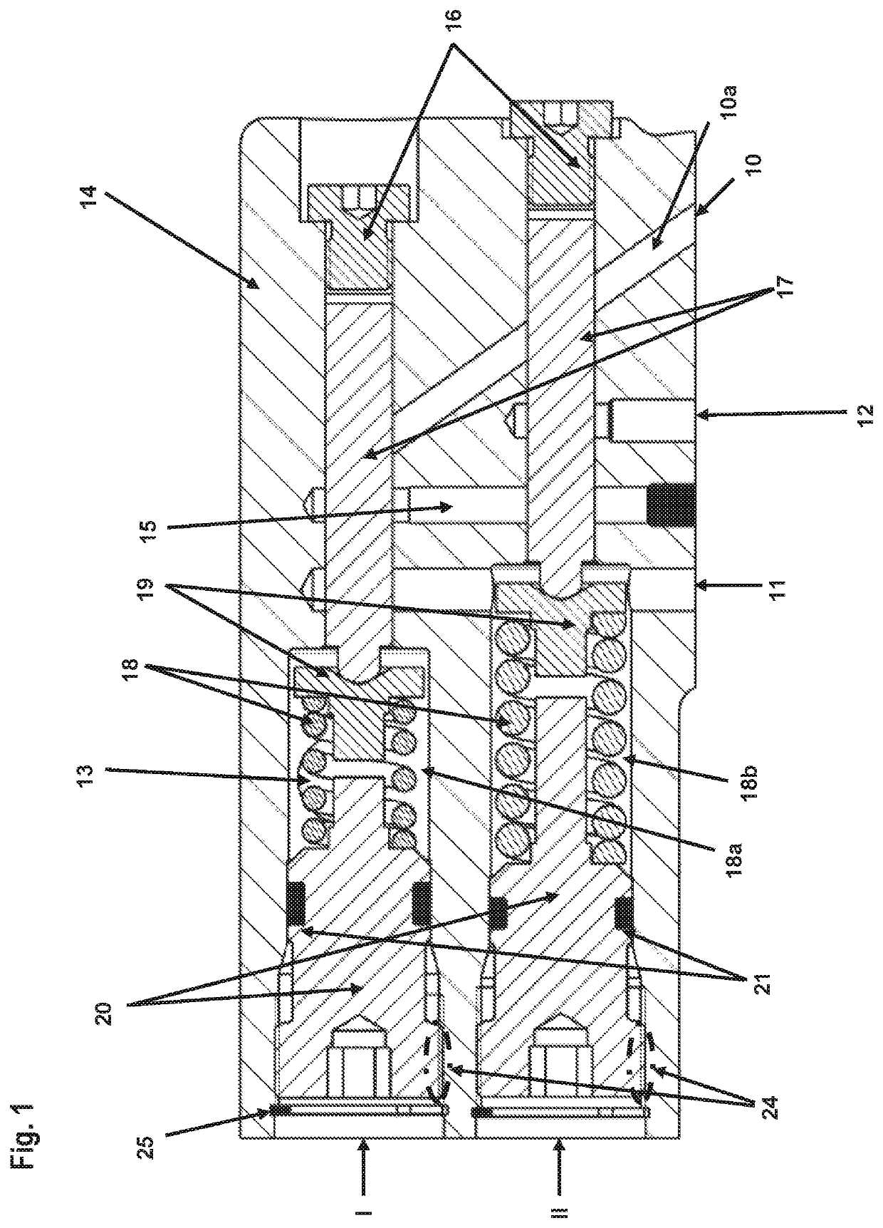
[0044]The hydraulic apparatus in accordance with the invention will be presented in the following with reference to an embodiment shown in FIGS. 1 to 4, wherein it is a hydraulic regulator having a load sensing regulator I and a pressure cut off II that are located in a common housing 14. The explanation of this embodiment takes place under the assumption that the hydraulic regulator is used to actuate the regulating apparatus of a hydraulic pump. The hydraulic regulator has four outer connectors 10, 11, 12, 13 to provide oil connections, namely the connector 10 to the high pressure output of the hydraulic pump to be regulated, the connector 11 to the tank return, a connector 12 to the regulating apparatus of the hydraulic pump, and a connector 13 for the supply of the external control pressure. The load sensing regulator I and the pressure cut off II are here connected to one another via a common bore 15 that is sealed to the outside.

[0045]Both regulator axles, i.e. that of the loa...


PUM


Abstract

The present invention relates to a hydraulic apparatus, in particular to a hydraulic valve or to a hydraulic regulator, having a housing, at least one piston axially displaceably supported in a housing bore, and a respective at least one compression spring acting on the at least one piston, wherein at least one externally accessible regulating screw is adjustable within the housing bore to set the preload of the compression spring in the axial direction, wherein the adjustment distance of the at least one regulating screw is divided into at least two adjustment ranges and the torque to be applied for the adjustment of the regulating screw is larger in a second adjustment range than in a first adjustment range.

Description

[0001]This application claims priority to Swiss Patent Application No. 00979 / 17 entitled “HYDRAULISCHE VORRICHTUNG, INSBESONDERE HYDRAULIKVENTIL ODER HYDRAULIKREGLER,” filed Jul. 27, 2017, the entire contents of which is hereby incorporated by reference in its entirety for all purposes.TECHNICAL FIELD[0002]The invention relates to a hydraulic apparatus, in particular to a hydraulic valve or to a hydraulic regulator, having a housing, at least one piston axially displaceably supported in a housing bore, and a respective at least one compression spring acting on the at least one control spool, wherein at least one externally accessible regulating screw is adjustable within the housing bore to set the preload of the compression spring in the axial direction.BACKGROUND AND SUMMARY[0003]In the following explanation, the term common in this area of control spool is used instead of the generalized term piston in the text passages in which the laying open of the invention relates to the app...

Claims


Application Information

Patent Timeline
IPC IPC(8): F15B13/04F04B49/00F15B13/02F04B49/22F04B49/08F16K17/04F16K17/06F16F1/12F04B53/10F15B13/14
CPCF15B13/0417F04B53/10F16K17/06F15B13/0402F15B13/024F16K17/0473F04B49/08F04B49/22F04B49/00F16F1/121F15B2211/422F15B13/14F15B2211/40515F15B2211/522F15C3/02F16K3/18F16K3/34
Inventor GEISSLER, LENNARDWOHLHAUSER, PATRICK
Owner LIEBHERR MACHINES BULLE
Features
  • Generate Ideas
  • Intellectual Property
  • Life Sciences
  • Materials
  • Tech Scout
  • Unparalleled Data Quality
  • Higher Quality Content
  • 60% Fewer Hallucinations
Learn More