Shield terminal and shield connector

a shield connector and shield terminal technology, applied in the direction of coupling device connection, coupling contact member, coupling device details, etc., can solve the problems of not being able to maintain tubular shape, not being able to sufficiently ensure shielding, and reducing the strength around the butting edges of tubular fittings, so as to improve the shielding property and the shielding effect, the effect of not reducing the strength

Active Publication Date: 2020-11-17
SUMITOMO WIRING SYST LTD
View PDF10 Cites 2 Cited by
  • Summary
  • Abstract
  • Description
  • Claims
  • Application Information

AI Technical Summary

Benefits of technology

[0006]The resilient and fixed contacts contact the mating outer conductor with the mating outer conductor fit in the tubular fitting. Thus, a return current generated in the outer conductor terminal when an electrical signal flows in the inner conductor terminal can be caused to flow to the mating outer conductor via the resilient contact and the fixed contact. In addition, the fixed contact has the embossed shape and can be formed without making a hole. Thus, as compared to a configuration in which a contact is formed with a hole by cutting and raising, a strength around the butting edges in the tubular fitting is not reduced. In this way, the circumferential edges of the tubular fitting will not separate due to a lack of strength and a shielding property for the inner conductor terminal by the outer conductor terminal does not deteriorate.
[0007]The tubular fitting may include two resilient contacts and two fixed contacts. According to this configuration, the outer conductor terminal is in contact with the mating outer conductor at four points. Thus, the number of flowing paths of the return current from the tubular fitting to the mating outer conductor increases and the shielding property can be improved as compared to a configuration in which one resilient contact and one fixed contact are provided.
[0008]The two fixed contacts may be formed respectively on opposite circumferential sides of the butting edges. The resilient contacts may be formed respectively at positions radially facing the fixed contacts in the tubular fitting. Accordingly, the resilient contacts and the fixed contact points can be arranged while being spaced large distances in the circumferential direction of the tubular fitting. Thus, the return current can flow efficiently from the outer conductor terminal to the mating outer conductor and the shielding property can be improved.

Problems solved by technology

However, if the cutouts (holes) are near the butting portions in the tubular fitting, strength around the butting portions is reduced.
Thus, the butting portions easily are separated and it may not be possible to maintain the tubular shape.
In this way, it may not be possible to sufficiently ensure a shielding property for the inner conductor terminal by the outer conductor terminal.

Method used


Image

  • Shield terminal and shield connector
  • Shield terminal and shield connector
  • Shield terminal and shield connector

Examples


Embodiment Construction

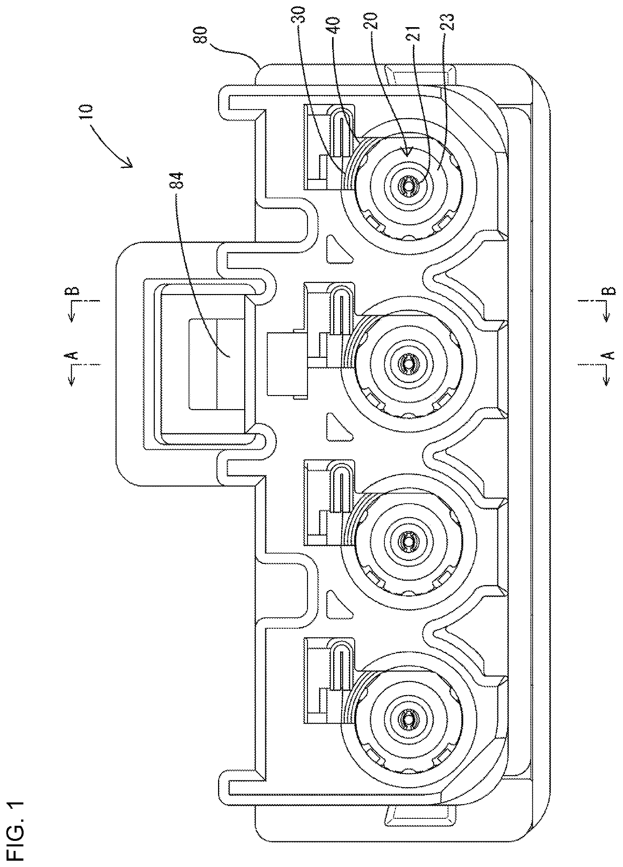
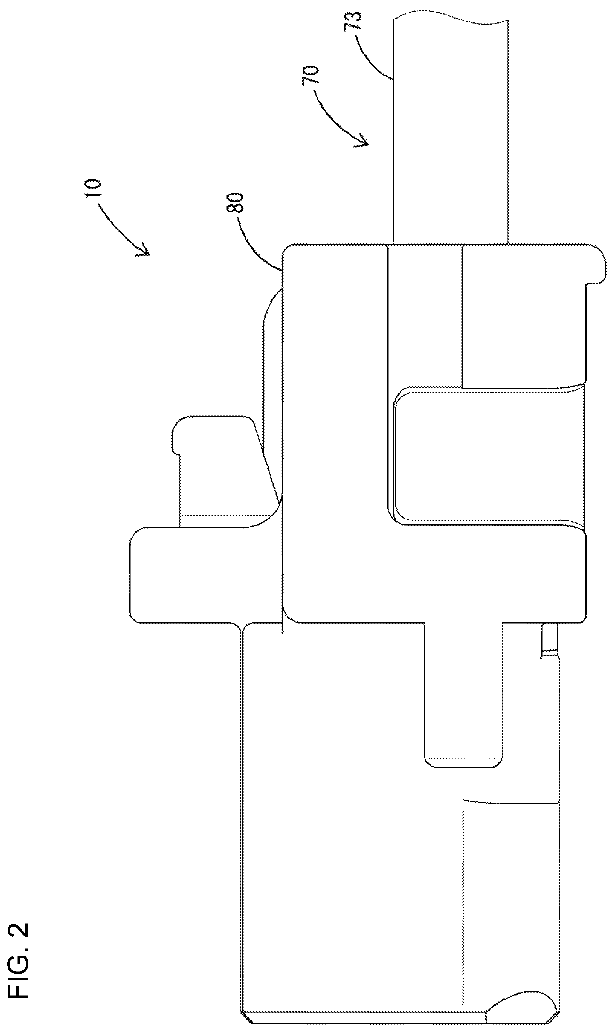
[0023]An embodiment of the invention is described with reference to FIGS. 1 to 13. A shield connector 10 of this embodiment is installed in a vehicle and is used in high-speed communication between in-vehicle electrical components. Note that, in the following description of each connector, an end facing a mating connector to be connected is referred to as a front concerning a front-rear direction. For example, a left side of FIG. 2 is referred to as a front. Further, upper and lower sides are based on a vertical direction of FIGS. 1 and 10.

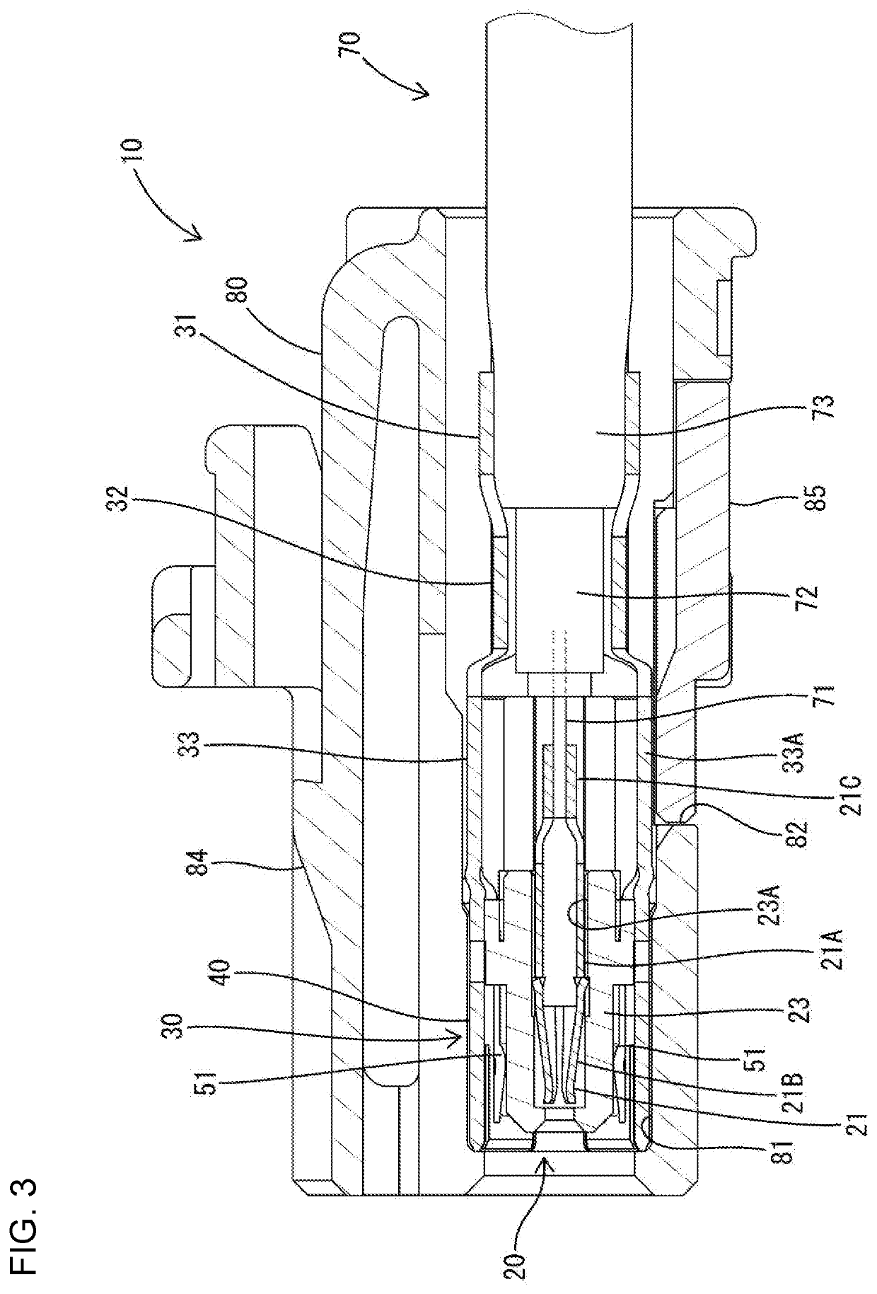
[0024]As shown in FIGS. 1, 3 and 4, the shield connector 10 includes shield terminals 20 and a connector housing 80 for accommodating the shield terminals 20. The shield connector 10 is configured as a so-called female connector and is connected to a mating connector 110 configured as a male connector. The shield terminal 20 includes an inner conductor terminal 21, an outer conductor terminal 30 surrounding the inner conductor terminal 21 and a di...


PUM


Abstract

A shield terminal (20) includes an inner conductor terminal (21) and an outer conductor terminal (30) surrounding the inner conductor terminal (21) and having a tubular fitting portion (400 to which a mating outer conductor (130) is fit. The tubular fitting portion (40) includes butting edges (41) to be butted against each other on both circumferential edge parts (41A, 41B), fixed contact point portions (42) formed to have an embossed shape in a butting-side half circumference portion (C1), the fixed contact point portions (42) contacting the mating outer conductor (130), and resilient contact portions (51) formed by cutting and raising parts of an opposite-side half circumference portion (C2) on a side opposite to the butting-side half circumference portion (C1), the resilient contact portions (51) resiliently contacting the mating outer conductor (130).

Description

BACKGROUNDField of the Invention[0001]The invention relates to a shield terminal and a shield connector.Related Art[0002]A shield terminal disclosed in Japanese Unexamined Patent Publication No. 2018-67496 includes an inner conductor terminal, a dielectric for accommodating the inner conductor terminal and an outer conductor terminal surrounding the dielectric. The inner conductor terminal is fixed conductively to an inner conductor of a shielded cable. The dielectric is interposed between the inner conductor terminal and the outer conductor terminal. The outer conductor terminal includes a tubular fitting to be fit to a mating outer conductor terminal inserted inside. The tubular fitting portion is maintained in a hollow cylindrical shape with both circumferential ends butted against each other. The outer conductor terminal is formed with four resilient contacts along a circumferential direction. Each resilient contact has both front and rear ends in an axial direction integrally c...

Claims


Application Information

Patent Timeline
Patent Type & Authority Patents(United States)
IPC IPC(8): H01R13/6583H01R9/05H01R13/6593H01R13/6582H01R13/58
CPCH01R13/6582H01R9/0524H01R13/5812H01R13/6593H01R13/6583H01R13/11H01R24/40H01R4/185H01R9/0518H01R13/4223H01R2103/00
Inventor HASHIMOTO, NORIHITOKANEMURA, KEISUKEKUBOTA, MOTOKIKANG, LIPINGMITSUI, SHOHEIYAMANAKA, WATARUKASUGA, MASANOBUHIRANO, AIYAMADA, RYO
Owner SUMITOMO WIRING SYST LTD
Why Eureka
Try Eureka