
Lighting assembly with diffusor

a diffusor and light assembly technology, applied in the field of lighting, can solve the problems of uneven output over the front surface of the diffusor, uneven light output from leds, and uneven light outpu

Active Publication Date: 2020-11-24
LUMILEDS
View PDF18 Cites 0 Cited by
  • Summary
  • Abstract
  • Description
  • Claims
  • Application Information

AI Technical Summary

Benefits of technology

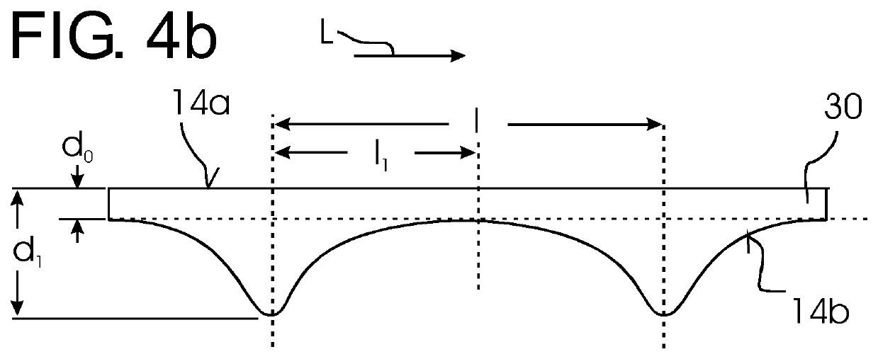
The invention provides a lighting assembly with a compact arrangement that achieves a more homogeneous appearance. The thin diffusor element used in the assembly achieves high efficiency, with satisfactory homogeneity values even at a relatively thin level. Different levels of optical diffusion may be achieved by varying the thickness of the diffusor element, which can also be combined with a variation in particle density and thickness. A reflective housing is preferred to improve efficiency, covering the inner surfaces of the housing oriented towards the LED lighting elements and aiming to cover the lateral and bottom surfaces of the lighting assembly, but not the top surface of the diffusor.

Problems solved by technology

However, while many lighting applications require light output to be spread over a larger area, the light output from LEDs is rather concentrated to small areas.
If a plurality of LEDs is used, these are generally arranged at a certain distance from each other due to thermal limitations and for cost reasons.
However, the arrangement of individual LEDs behind the diffusor is still visible in many cases, such that the light output over the front surface of the diffusor is not very homogeneous, leading to a spotty appearance.
While a very thick diffusor may achieve better homogeneity, this will lead to reduced overall efficiency.

Method used


Image

  • Lighting assembly with diffusor
  • Lighting assembly with diffusor
  • Lighting assembly with diffusor

Examples


Embodiment Construction

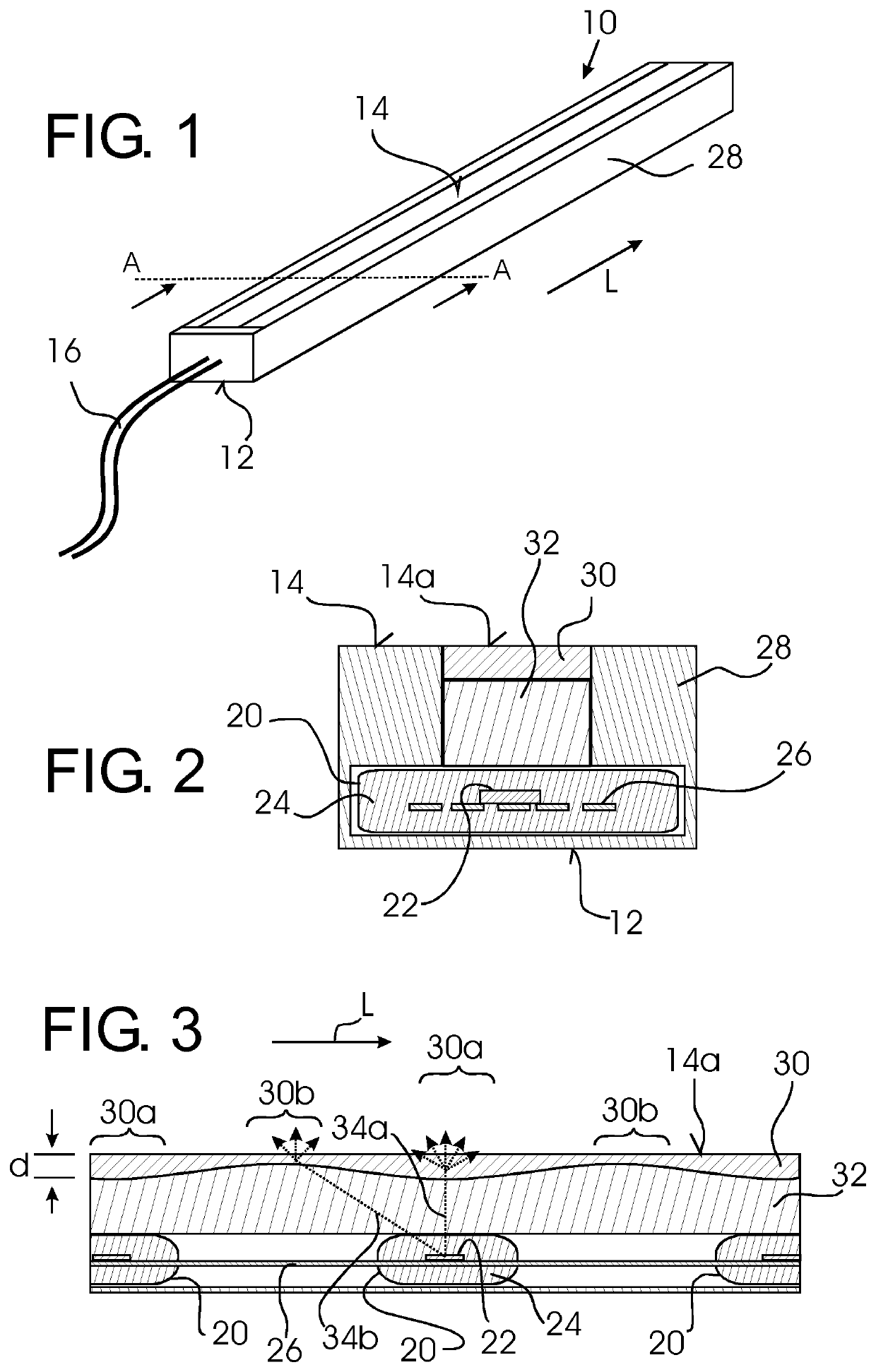
[0035]An elongate lighting assembly 10 is shown in FIG. 1, comprising a bottom surface 12 and a top surface 14 from which light is emitted. Electrical connections 16 shown schematically deliver electrical operating power to the lighting assembly 10.

[0036]The lighting assembly 10 is of particularly small dimensions, in a preferred example with a height measured from the bottom surface 12 to the top surface 14 of only 4 mm and a width of only 7 mm.

[0037]The length in a longitudinal direction L may vary, but will be significantly greater than the width, e.g. at least 10 times greater.

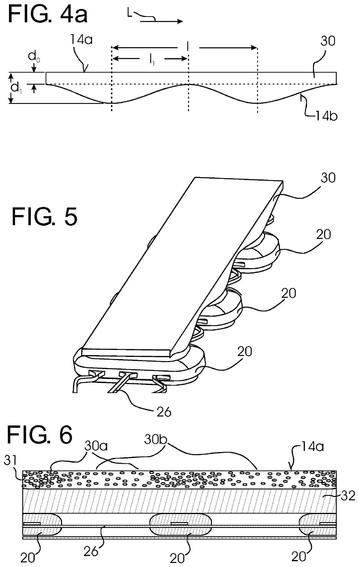
[0038]In the interior of the lighting assembly 10, as shown in the cross-section of FIG. 2 and longitudinal-section of FIG. 3, a plurality of LEDs 20 are arranged in a line equally spaced along the longitudinal direction L of the lighting assembly 10. In the example shown, each LED 20 comprises a LED die 22 surrounded by a housing 24. The LEDs 20 are electrically interconnected by electrical conductors for...


PUM

PropertyMeasurementUnit
heightaaaaaaaaaa
heightaaaaaaaaaa
widthaaaaaaaaaa

Abstract

A lighting assembly includes at least two LED elements arranged at a distance from each other. A diffusor element extends over the LED lighting elements. The diffusor element comprises first diffusion portions arranged in front of the LED lighting elements and second diffusion portions arranged in between the first diffusion portions. The first diffusion portions are disposed to cause a stronger optical diffusion than the second diffusion portions, thereby providing a more homogeneous appearance of light emitted from the diffusor element.

Description

FIELD OF THE INVENTION[0001]The invention relates to the field of lighting, and more specifically to a lighting assembly.BACKGROUND OF THE INVENTION[0002]LEDs are used today for an increasing number of lighting applications due to advantageous properties such as high energy efficiency, compact size and long lifetime. However, while many lighting applications require light output to be spread over a larger area, the light output from LEDs is rather concentrated to small areas. If a plurality of LEDs is used, these are generally arranged at a certain distance from each other due to thermal limitations and for cost reasons.[0003]In order to obtain a relatively homogeneous light output from a plurality of LEDs, it is generally known to position a diffusor element in front of the LEDs. However, the arrangement of individual LEDs behind the diffusor is still visible in many cases, such that the light output over the front surface of the diffusor is not very homogeneous, leading to a spott...

Claims


Application Information

Patent Timeline
Patent Type & Authority Patents(United States)
IPC IPC(8): F21V3/06F21S4/22F21K9/65F21S4/28F21Y103/10F21Y115/10
CPCF21V3/0625F21S4/22F21S4/28F21K9/65F21Y2103/10F21Y2115/10F21K9/64
Inventor CROMPVOETS, FLORIS MARIA HERMANSZKLEIJNEN, CHRISTIANPETERS, RALPH HUBERTLIND, ADAMEINIG, ROB BASTIAAN MARIA
Owner LUMILEDS
Learn More