High color rendering white light emitting devices and high color rendering photoluminescence compositions

a technology of light emitting devices and compositions, applied in the direction of climate sustainability, radiation control devices, semiconductor devices, etc., can solve the problems of conversion efficiency and performance suffer particularly, and achieve the effect of high color rendering light emitting devices, higher conversion efficiency and luminous efficacy

Active Publication Date: 2020-11-24
BRIDGELUX INC
View PDF18 Cites 0 Cited by
  • Summary
  • Abstract
  • Description
  • Claims
  • Application Information

AI Technical Summary

Benefits of technology

[0007]In this way, devices formed in accordance with the invention can be configured to produce white light that meets current standards for CRI Ra, CRI R8 and CRI R9 and have a conversion efficiency (CE) and luminous efficacy (LE) that are superior than those of known devices. More particularly, devices according to the invention comprising a red, a yellow to green, and a narrow-band red photoluminescence material can produce white light that meets the current standards of CRI Ra of about 90, a CRI R8 of about 72 and a CRI R9 of about 50 and have a conversion efficiency / luminous efficacy (for example 330 lm / W to 350+ lm / W) depending on color temperature) that are superior to known devices.
[0027]In accordance with the invention, there is also provided a photoluminescence composition comprising a combination of a red photoluminescence material, a yellow to green photoluminescence material and a narrow-band red photoluminescence material enables high color rendering light emitting devices to be implemented that produce white light meeting current lighting standards namely: CRI Ra≥90 (Energy Star), CRI R8 minimum 72 (California Energy Commission Title 20 code) and CRI R9 minimum 50 (CEC Title 24 code). Moreover, the light emitting devices in accordance with the invention also exhibit a higher conversion efficiency and luminous efficacy compared with current light emitting devices.

Problems solved by technology

However, depending on their composition and intrinsic properties, their performance can suffer particularly in terms of luminous efficacy (LE) and / or conversion efficiency (CE).

Method used


Image

  • High color rendering white light emitting devices and high color rendering photoluminescence compositions
  • High color rendering white light emitting devices and high color rendering photoluminescence compositions
  • High color rendering white light emitting devices and high color rendering photoluminescence compositions

Examples


Embodiment Construction

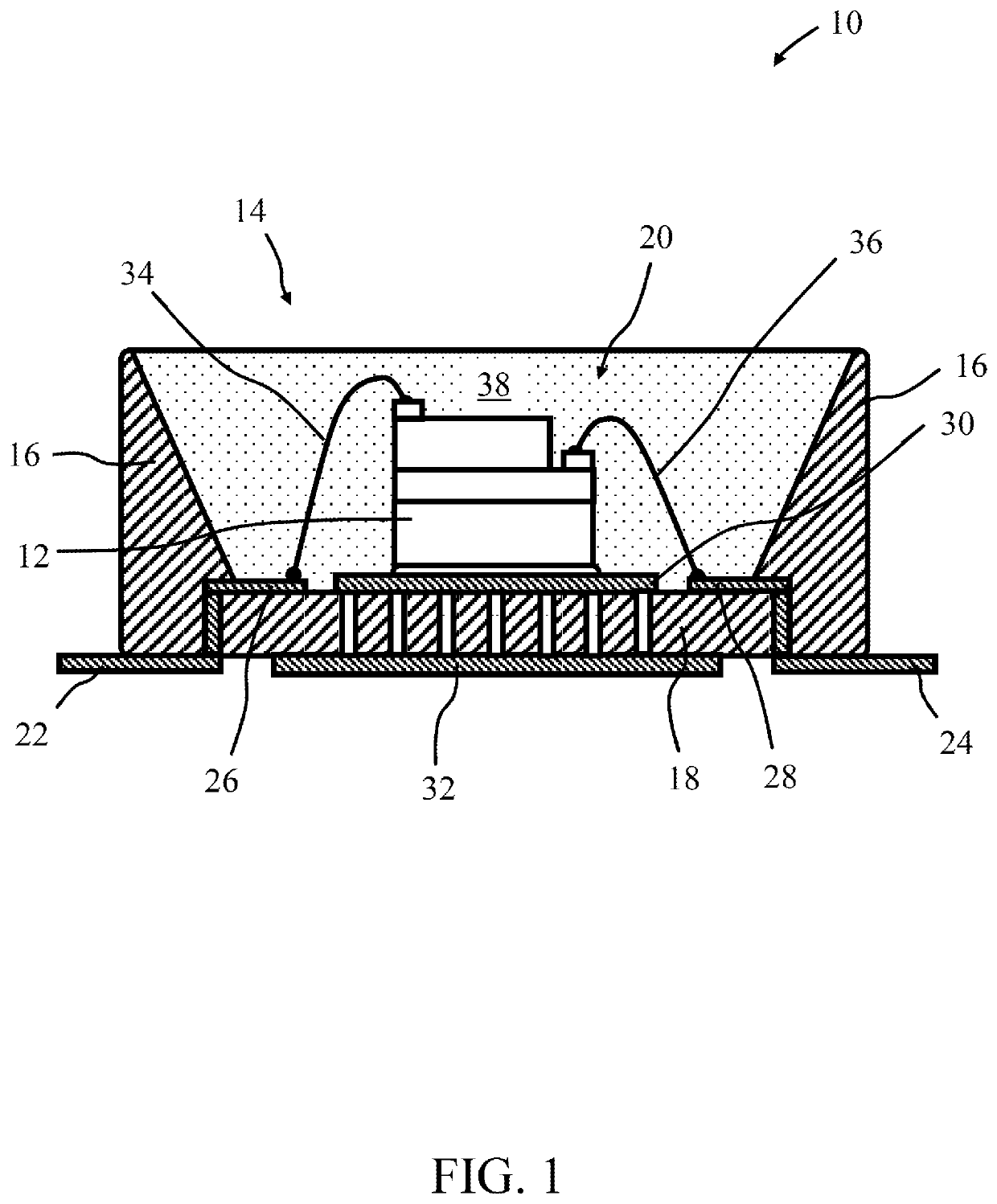
[0043]Embodiments of the present invention will now be described in detail with reference to the drawings, which are provided as illustrative examples of the invention so as to enable those skilled in the art to practice the invention. Notably, the figures and examples below are not meant to limit the scope of the present invention to a single embodiment, but other embodiments are possible by way of interchange of some or all of the described or illustrated elements. Moreover, where certain elements of the present invention can be partially or fully implemented using known components, only those portions of such known components that are necessary for an understanding of the present invention will be described, and detailed descriptions of other portions of such known components will be omitted so as not to obscure the invention. In the present specification, an embodiment showing a singular component should not be considered limiting; rather, the invention is intended to encompass ...


PUM

PropertyMeasurementUnit
color temperatureaaaaaaaaaa
CRIaaaaaaaaaa
dominant wavelengthaaaaaaaaaa

Abstract

A exemplary light emitting device includes an excitation source operable to generate excitation light with a dominant wavelength in a range 450 nm to 470 nm; a red photoluminescence material which generates light with a peak emission wavelength in a range 600 nm to 620 nm with a full width at half maximum emission intensity greater than 70 nm and less than 80 nm; a yellow to green photoluminescence material which generates light with a peak emission wavelength in a range 530 nm to 550 nm; and a narrow-band red photoluminescence material which generates light with a peak emission wavelength in a range 625 nm to 635 nm with a full width at half maximum emission intensity greater than about 5 nm and less than about 25 nm.

Description

FIELD OF THE INVENTION[0001]Embodiments of the present invention are directed to light emitting devices comprising photoluminescence wavelength conversion materials. More particularly, although not exclusively, embodiments concern light emitting devices and photoluminescence compositions for generating white light with high color rendering properties including a general CRI Ra of greater than or equal to 90.BACKGROUND OF THE INVENTION[0002]White light emitting LEDs (“white LEDs”) include one or more photoluminescence materials (typically inorganic phosphor materials), which absorb a portion of the blue light emitted by the LED and re-emit light of a different color (wavelength). The portion of the blue light generated by the LED that is not absorbed by the phosphor material combined with the light emitted by the phosphor provides light which appears to the eye as being white in color. Due to their long operating life expectancy (>50,000 hours) and high luminous efficacy (100 lume...

Claims


Application Information

Patent Timeline
Patent Type & Authority Patents(United States)
IPC IPC(8): H01L27/146C09K11/77H01L27/15C09K11/57C09K11/08
CPCC09K11/7774C09K11/572C09K11/7792C09K11/0883H01L27/14645H01L27/15C09K11/616C09K11/617Y02B20/00C09K11/77347C09K11/77924C09K11/77342C09K11/77348
Inventor WANG, GANGLI, YI-QUN
Owner BRIDGELUX INC
Why Eureka
Try Eureka