Adapter for self-alignment in 3 dimensional planes for passive prosthetics

a technology of adapters and prosthetic legs, applied in the field of adapters in prosthetic legs, can solve the problems of inability to sustain, tendonitis and lower back pain, time-consuming and subjective, etc., and achieve the effects of enhancing agility and performance, and reducing the time of prosthetist car

Active Publication Date: 2020-12-08
IMPULSE TECH
View PDF28 Cites 0 Cited by
  • Summary
  • Abstract
  • Description
  • Claims
  • Application Information

AI Technical Summary

Benefits of technology

[0024]Even though our adapter is a passive mechanism, it can be applied to active (robotic or computer-controlled) prosthetics for enhanced agility and performance. A unique feature of the invention is that it can manufactured assembly-free or as one-piece through the 3D printing technique.
[0025]Any prosthetic leg fitted with the invented mechanism will require little prosthetist attention. Therefore, the advantage is drastic reduction in prosthetist care time. Over the usage, the patient will experience less pain and discomfort, exert less physical labor in walking and prevent long-term physiological damages. Since the invention is a passive mechanism, and is amenable to 3D printing, it will be significantly lower cost compared to active prosthetics.
[0031](e) The product mimics the plantarflexion and dorsiflexion stiffness in a natural leg, therefore is effective for slopes, stairs and uneven terrain.

Problems solved by technology

It is time consuming and subjective because of the variability in human gait as well as the adaptability to misalignment.
However, this is not sustainable and in the longer term, problems range from tendonitis and lower back pain to amputation of the second leg or higher mortality rate in the case of diabetes.
Since the socket axis and ground reaction force (GRF) direction can have a large range of variation during the gait cycle, dynamic alignment is challenging, even with robotic or microprocessor-controlled prostheses.
While these aligners possess adequate degrees of freedom in motion, they do not self-align.
This is a major problem because the prosthetist never makes all the required adjustments at the same time.
Rather, these are achieved through many time-consuming iterations from the prosthetist and the amputee.
The human to human variance does not allow the prosthetist to develop a scheme for mitigating the dynamic alignment problem.
As a result, the problems of accurate diagnosis and remediation remain intractable.
This is not the optimal solution, because for real-time alignment, highly non-linear stiffness mimicking natural ankle or foot is needed.
Else, alignment is not possible.
Since all existing passive ankle foot have fixed stiffness, they are not able to provide the desired alignment effects.
None of the alignment adapters in the literature allows alignment motion in all three planes.
Two or more such adapters may be combined to provide such complete motion, but that increases size and weight.
Since they are rigid elements, none of the alignment adapters allow tunable and variable stiffness like a natural leg.
Similarly, they do not allow rotational compliance like an ankle.
Sagittal plane has the highest moment, but even small misalignment in other planes are equally painful.
Finally, none of the adapters or ankles or ankle-foots are designed to be assembly free or one-piece product.
Or in other words, they are not amenable to 3D printing.

Method used


Image

  • Adapter for self-alignment in 3 dimensional planes for passive prosthetics
  • Adapter for self-alignment in 3 dimensional planes for passive prosthetics
  • Adapter for self-alignment in 3 dimensional planes for passive prosthetics

Examples


first embodiment

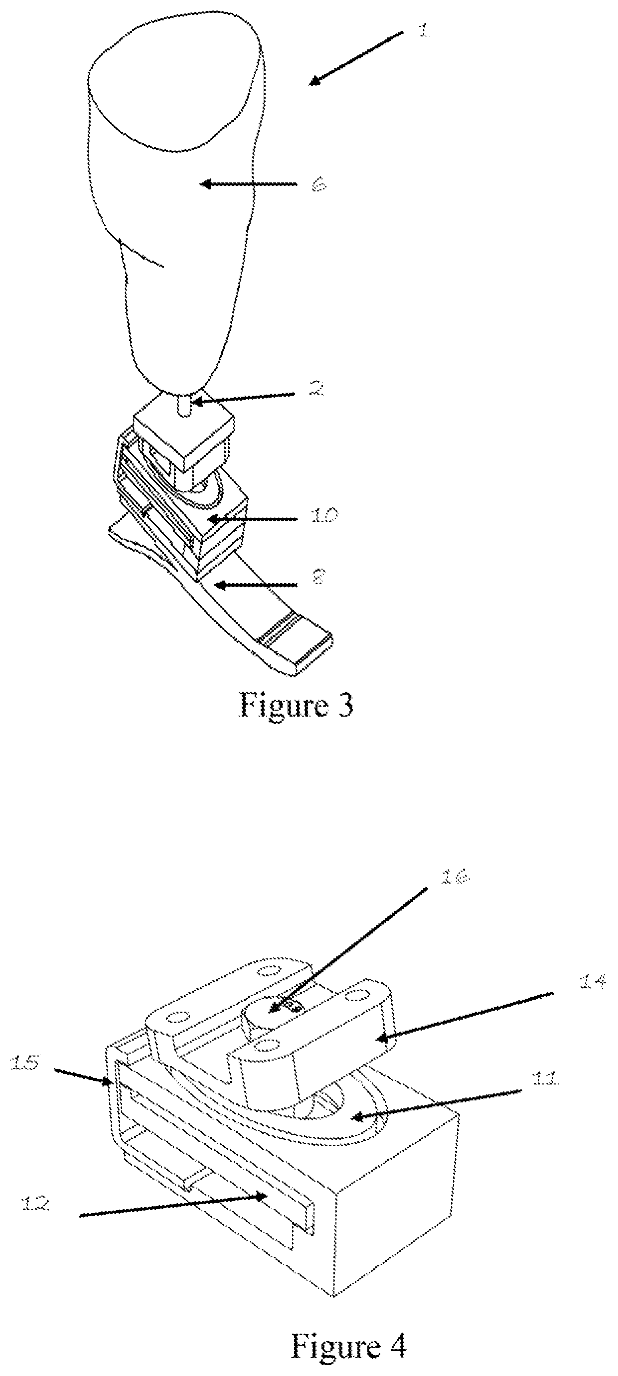
[0080]our self-aligning adapter shown in FIGS. 3 through 6 is an add-on component. This is a self-aligning adapter that can be mounted on any commercially available foot. Essentially, the adapter is a combination of two planar compliant 6 degrees of freedom springs with unique assembly that allows them to behave non-linearly compliant during heel-rocker and stiff during ankle-rocker phases of the gait. However, other different embodiments of the same core design philosophy are possible. Also, these embodiments can involve different materials (such as aluminum alloys, titanium alloys, carbon fiber composites to name a few).

[0081]A different embodiment of our self-aligning adapter 10 is configuration 20 shown in FIGS. 17 and 18. FIG. 17 shows an exploded view, while FIG. 18 is an end view. This embodiment is made stiffer by modifying spiral geometry and employing a different material thereby rendering the use of stiffener 15 unnecessary.

[0082]The embodiments shown so far are for the p...

embodiment 30

[0083]One such embodiment 30 is shown in FIGS. 19, 20 and 21. This embodiment has heel spring 31 similar to low stiffness spring 11 and a keel 32 which is functionally similar to high stiffness spring 12. This embodiment has a different connector 33 on the top to connect to the pylon 6 or socket 2.

[0084]Another embodiment of our self-aligning adapter 10, integrated to an ankle-foot is configuration 40, shown in FIGS. 22 and 23. Another embodiment 50 is shown in FIGS. 24 and 25. These embodiments have two planar springs 41 and 42 or 51 and 52 that look different but have the same functionality. One spring 41, 51 is a low stiffness spring. The other spring 42, 52 is a high stiffness spring. The spring stiffener 45, 55 is shown in each of these embodiments as wire-like structures to reduce weight, but solid structures like spring stiffener 15 shown in FIG. 4 can also be used. All these embodiments utilize the connector 14 as well as bolt 16 and nut 17 that are in the first embodiment.

embodiment 60

[0085]Another possible embodiment 60 is shown in FIGS. 26 and 27 where the heel part of the foot is modified to function as the low stiffness spring 61 and another part of the foot act as the high stiffness spring 62. A non-linear stiffener 65 is connected between the two springs 61 and 62. There is a different connector 66 that is used to attach this embodiment to a pylon or leg socket. In this embodiment the foot keel (top plate) itself works as the high stiffness spring 62. The heel part of the foot is attached to it through a planar compliant structure. This low stiffness 6 degree of freedom spring allows the heel to produce the biomimetic heel-rocker region. After that, the wire-like spring stiffeners 45 become taut, and the foot keel starts to deform to produce the ankle rocker phase. This design can be a one-piece (no assembly) product, hence no exploded view is shown.

[0086]In another possible embodiment 70 shown in FIGS. 28 and 29 the relative position of the two 6 degrees o...


PUM


Abstract

A self-adjusting adapter for a prosthetic leg having a foot and a leg socket has a low stiffness spring having a central opening, a high stiffness spring that has a central opening and is adjacent the low stiffness spring, a shaft or a bolt passing through the central opening in the low stiffness spring and the central opening in the high stiffness spring and a spring stiffener configured and positioned to restrain movement of the high stiffness spring relative to the low stiffness spring in a direction parallel to the low-stiffness spring. A connector for attaching the adapter to a leg socket is connected to the bolt or shaft and is capable of pivoting about an axis through the bolt or shaft. The adapter can be used an add-on component for existing prosthetic legs, or it can be integrated with foot design for the ankle-foot product category.

Description

CROSS-REFERENCE TO RELATED APPLICATION[0001]This application claims priority to U.S. Provisional Patent Application Ser. No. 62 / 814,533, filed on Mar. 6, 2019, the contents of which are incorporated herein by reference.STATEMENT REGARDING FEDERALLY SPONSORED RESEARCH AND DEVELOPMENT[0002]This invention was made with the United States government support under Small Business Innovative Research awards (DoD / DHA SBIR Phase I & II Contracts: W81XWH 17C 0102 & W81XWH 18C 0089). The United States government has certain rights in the invention.FIELD OF INVENTION[0003]The invention relates to adapters in prosthetic legs that allows certain range of motion to effectively act as a prosthetic ankle. The self-aligning adapter is an add-on component located between the foot and the pylon, thereby aligning the foot to the socket for amputee comfort. It thus also falls in the category of prosthetic ankle-foot, where the adapter is integrated with the foot.BACKGROUND OF THE INVENTION[0004]Prosthetic...

Claims


Application Information

Patent Timeline
Patent Type & Authority Patents(United States)
IPC IPC(8): A61F2/66A61F2/76A61F2/50
CPCA61F2/76A61F2/6607A61F2002/5078A61F2002/503A61F2/66A61F2002/6614A61F2002/6692
Inventor HAQUE, MD AMANULRAJULA, VAMSIDHAR REDDYKAMRUNNAHAR, MST (KAMRUN)
Owner IMPULSE TECH
Why Eureka
Try Eureka