
Back-to-back selectable one-way clutches for engine disconnect devices of motor vehicle powertrains

a technology of motor vehicles and disconnect devices, which is applied in the direction of hybrid vehicles, fluid couplings, gearing, etc., can solve the problems of the multiplicity of impeller torque, and achieve the effects of reducing the number of engine disconnects

Active Publication Date: 2020-12-15
GM GLOBAL TECH OPERATIONS LLC
View PDF51 Cites 5 Cited by
  • Summary
  • Abstract
  • Description
  • Claims
  • Application Information

AI Technical Summary

Benefits of technology

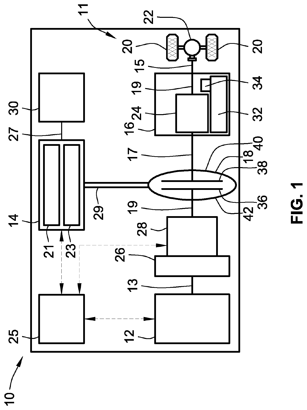
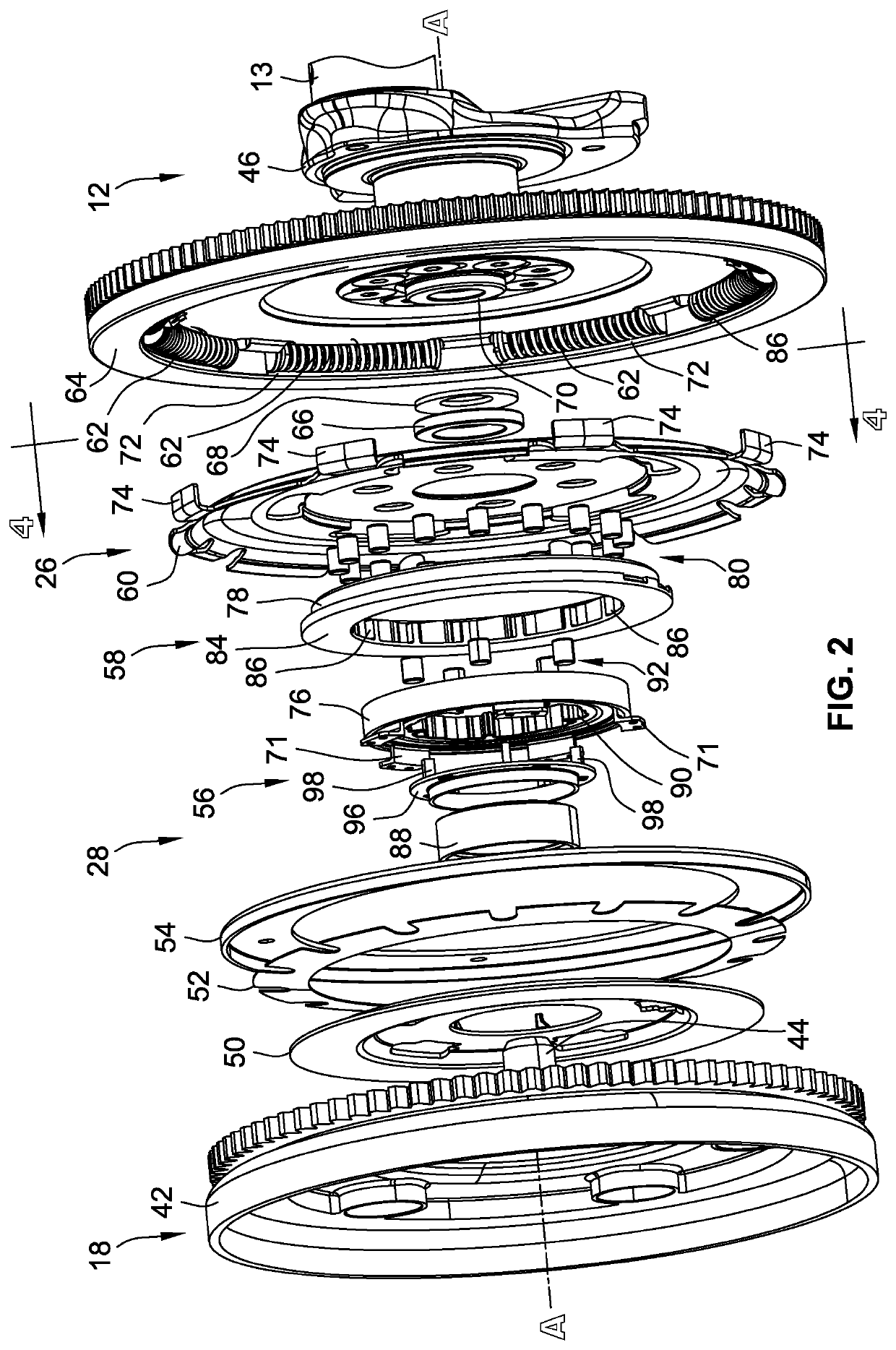
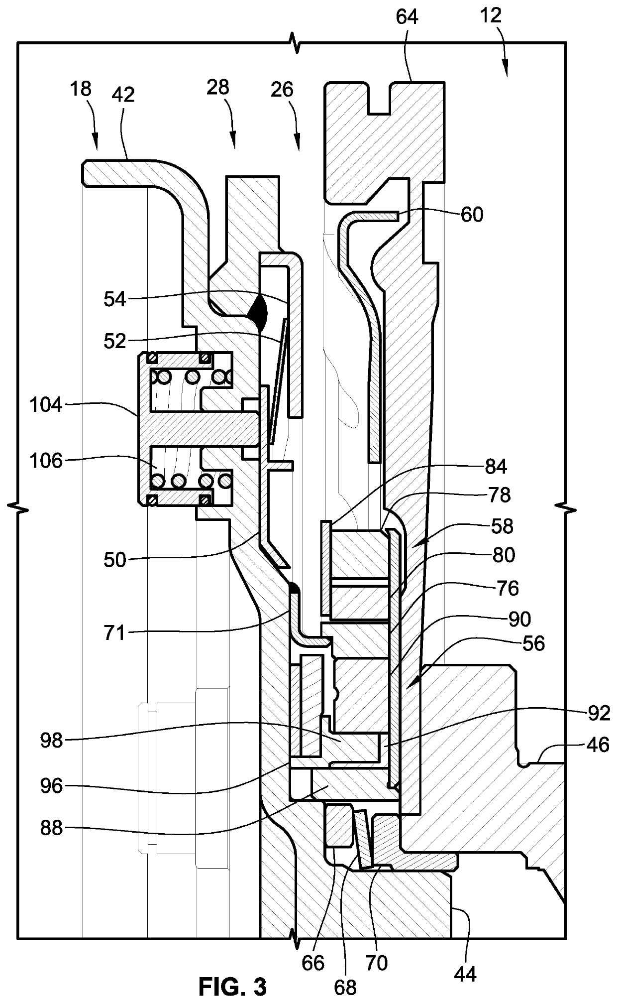
The patent text discusses various powertrain configurations and control methods for vehicles. These configurations help to improve the performance and efficiency of vehicles by reducing noise and vibration, and by minimizing fuel economy and emissions. One of the key features of the text is the inclusion of a torque converter with an internal clutch mechanism (TCC) to reduce slip and improve efficiency. Another configuration is the parallel two-clutch (P2) architecture, which eliminates the use of additional motor / generators and reduces complexity and cost. The text also mentions the use of disconnect devices to improve powertrain response time and reduce noise and vibration during transient vehicle operations. The proposed designs also minimize packaging space requirements by reducing the axial length of the engine disconnect device. Overall, the patent text provides technical solutions to improve the performance and efficiency of vehicle powertrains while minimizing cost and space requirements.

Problems solved by technology

A large difference in speed between the impeller and turbine results in torque multiplication of the impeller torque, as for example when the vehicle is accelerating from rest with the engine running.

Method used


Image

  • Back-to-back selectable one-way clutches for engine disconnect devices of motor vehicle powertrains
  • Back-to-back selectable one-way clutches for engine disconnect devices of motor vehicle powertrains
  • Back-to-back selectable one-way clutches for engine disconnect devices of motor vehicle powertrains

Examples


Embodiment Construction

[0027]This disclosure is susceptible of embodiment in many different forms. Representative embodiments of the disclosure are shown in the drawings and will herein be described in detail with the understanding that these embodiments are provided as an exemplification of the disclosed principles, not limitations of the broad aspects of the disclosure. To that extent, elements and limitations that are described, for example, in the Abstract, Introduction, Summary, and Detailed Description sections, but not explicitly set forth in the claims, should not be incorporated into the claims, singly or collectively, by implication, inference or otherwise.

[0028]For purposes of the present detailed description, unless specifically disclaimed: the singular includes the plural and vice versa; the words “and” and “or” shall be both conjunctive and disjunctive; the words “any” and “all” shall both mean “any and all”; and the words “including,”“containing,”“comprising,”“having,” and the like, shall e...


PUM


Abstract

Presented are dual-clutch engine disconnect devices, methods for making / using such disconnect devices, and motor vehicles equipped with such disconnect devices. An engine disconnect device for a vehicle includes a first one-way clutch (OWC) with concentric inner and outer races and torque elements interposed between and transferring torque across these races in a first direction. The first outer race rigidly attaches to a damper plate for common rotation therewith, and the first inner race rigidly attaches to a pump cover of a torque converter for common rotation therewith. A second OWC, which concentrically aligns within the first OWC, includes concentric inner and outer races with torque elements interposed between and transferring torque across these races in a second direction. The second outer race is splined to the first inner race for common rotation with the pump cover. The second inner race rigidly attaches to the damper plate for common rotation therewith.

Description

INTRODUCTION[0001]The present disclosure relates generally to motor vehicle powertrains. More specifically, aspects of this disclosure relate to engine disconnect devices with attendant control logic and hydraulic hardware for hybrid electric powertrains.[0002]Current production motor vehicles, such as the modern-day automobile, are originally equipped with a powertrain that operates to propel the vehicle and power the vehicle's onboard electronics. In automotive applications, for example, the vehicle powertrain is generally typified by a prime mover that delivers driving power through an automatic or manually shifted power transmission to the vehicle's final drive system (e.g., differential, axle shafts, road wheels, etc.). Automobiles have historically been powered by a reciprocating-piston type internal combustion engine (ICE) assembly due to its ready availability and relatively inexpensive cost, light weight, and overall efficiency. Such engines include two and four-stroke comp...

Claims


Application Information

Patent Timeline
Patent Type & Authority Patents(United States)
IPC IPC(8): B60K6/383F16D31/02F16D21/06B60W20/10F16H45/00F16D11/00F16H29/02
CPCB60K6/383F16H29/02F16D2011/008F16D31/02F16H2045/002B60W20/10F16D2021/0607F16D2500/1026B60K6/40B60K6/48B60K2006/4825F16D39/00F16D41/061F16D41/066F16H2045/0252F16H2045/0294Y02T10/62
Inventor LAHR, DEREK F.AYYANAR, VELMURUGANLI, DONGXULEE, CHUNHAO J.SAMIE, FARZADBRUDER, DMITRIY
Owner GM GLOBAL TECH OPERATIONS LLC
Learn More