Eureka AIR delivers breakthrough ideas for toughest innovation challenges, trusted by R&D personnel around the world.

Discharge pressure scale and lifting-lowering device having a discharge pressure scale of this type

Active Publication Date: 2020-12-22
HYDAC FLUITECHNIK GMBH
View PDF8 Cites 0 Cited by
  • Summary
  • Abstract
  • Description
  • Claims
  • Application Information

AI Technical Summary

Benefits of technology

The invention improves known discharge pressure maintenance components by making them travel to a closed state in a tightly sealing position, thereby preventing leakage flows. However, a pressure maintenance component can still be used to establish pressure compensation in the regulating or valve piston after the proportional valve has opened, in order to prevent distortion of the load pressure. To achieve this, a check valve for pressure compensation is integrated in the relevant drilled hole or pressure compensation channel, ensuring pressure is only passed on when the valve is in the seat and compensation is required.

Problems solved by technology

However, in practice it turned out that even the slightest irregular impressions on the valve seat create, due to the associated differential surfaces, pressure conditions, which no longer permit the regulating or valve piston to be opened safely.
Such irregular impressions, which result in varying seating and sealing geometries, are due to the fact that the valve piston of the pressure maintenance component during operation constantly strikes against the associated seat components in the valve housing and plastically deforms the valve components in this area.

Method used


Image

  • Discharge pressure scale and lifting-lowering device having a discharge pressure scale of this type
  • Discharge pressure scale and lifting-lowering device having a discharge pressure scale of this type

Examples


Embodiment Construction

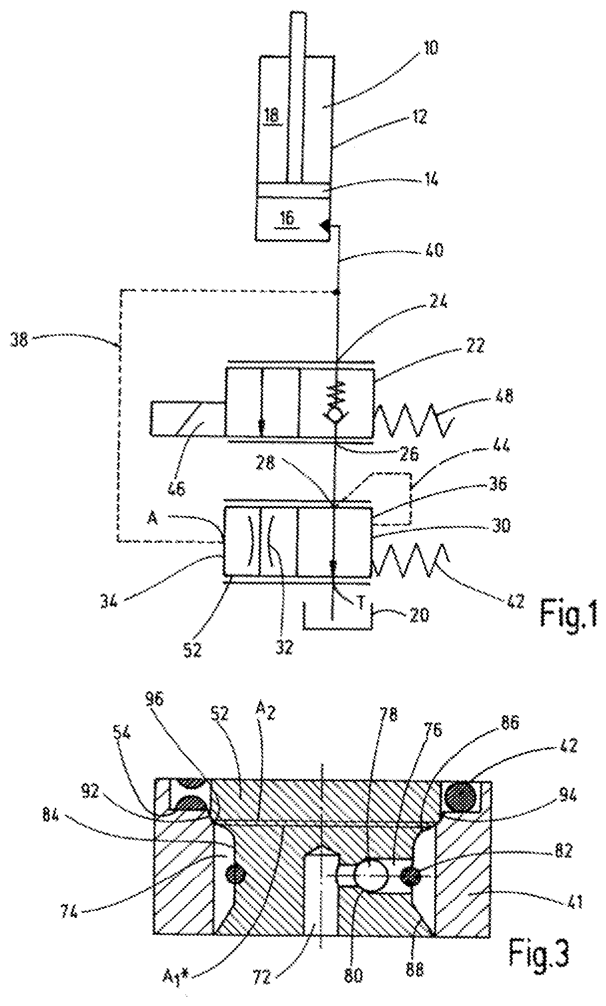
[0019]The hydraulic circuit diagram of FIG. 1 shows a hydraulic power cylinder 10, as it is regularly used for lifting and lowering applications, for instance in telehandlers, forklifts or lifting platforms. The power cylinder 10 has a longitudinally displaceable piston rod unit 14 in a housing 12, which unit divides the power cylinder 10 within the housing 12 into a piston chamber 16 and a rod chamber 18. A controllable motor pump unit, which lets fluid flow under pressure into the piston chamber 16, is used to extend the piston-rod unit 14 from the housing 12 of the power cylinder 10, for instance, for lifting a load. In this case, fluid is displaced via the rod chamber 18, which fluid is routed to a storage tank 20 via a suitable drain device. This type of control of power cylinders 10 for lifting-lowering applications is common in the prior art, i.e. will not be discussed in detail at this point.

[0020]Among other things, a proportional throttle valve 22 has inlet 24 permanently ...


PUM


Abstract

A discharge pressure scale (30) includes a valve housing (41) having a functional connector (A), a return flow connector (T) and a user connector (28). A valve piston (52) is guided such that it moves longitudinally against the effect of an energy accumulator (42), moving from a respective opening or regulating position, against a valve seat (94), into a closed position. The user connector (28) and return flow connectors (T) are separated from one another. The fluid pressure present at the user connector (28) can be guided onto a pressure-active surface (A1*) of the valve piston (52) by a pressure compensation device (70) in such a way that it moves into its respective opening or regulating position in a pressure-compensated manner due to the force of the energy accumulator (42).

Description

FIELD OF THE INVENTION[0001]The invention relates to a discharge pressure maintenance component, including at least one valve housing having at least three fluid connection ports in the form of a use port, a return port and a control port. A valve piston is longitudinally movably guided against the action of an energy storage device, and travels, starting from an individual opening or regulating position, against a valve seat into a closed position, in which the control port and the return port are separated from each other.BACKGROUND OF THE INVENTION[0002]For hydraulic control devices having a two-way flow regulator in a drain line towards the tank, the flow regulator has an orifice disk and a pressure maintenance component having a regulating piston. On the piston ends of control pressures can be applied in the control chambers. Shift jerking frequently cannot be avoided when hydraulic motors are operated unilaterally against a load because the regulating piston consumes a certain...

Claims


Application Information

Patent Timeline
IPC IPC(8): F15B13/04F15B11/05F15B13/02F15B13/01G05D16/20F15B13/00
CPCF15B13/01G05D16/2024F15B13/026F15B13/0405F15B13/0417F15B11/05F15B2211/41581F15B2211/465F15B2211/40515F15B2211/46F15B2211/426F15B2211/8606F15B2211/41563F15B2211/40569F15B2211/8613F15B2211/41554F15B2211/3055F15B2013/004
Inventor HILZENDEGEN, PHILIPPBILL, MARKUSHESS, MAXIMILIAN FELIX
Owner HYDAC FLUITECHNIK GMBH
Why Eureka
Eureka Blog
Learn More