Sealing of variable guide vanes

Inactive Publication Date: 2008-03-27
ABB TURBO SYST
View PDF4 Cites 24 Cited by
  • Summary
  • Abstract
  • Description
  • Claims
  • Application Information

AI Technical Summary

Benefits of technology

[0006] An adjusting device for a guiding device of a turbomachine is disclosed to the effect that despite the operation-related clearance between the moving parts of the guiding device, no leakage flow, or only a slight leakage flow, escapes through the bearings of the guide vanes.
[0009] According to the disclosure, an additional axial compression spring can ensure that the sealing sleeve is continuously pressed onto the guide vane mating contour, and that the axial gap and also the leakage flow are prevented as a result.

Problems solved by technology

With increasing bearing clearance, this leakage flow through the bearing bush increases.
This effect leads to a loss of turbine efficiency, and also to an increased noise development, as a rule in the form of a whistling which becomes more and more intense.

Method used


Image

  • Sealing of variable guide vanes
  • Sealing of variable guide vanes
  • Sealing of variable guide vanes

Examples


Embodiment Construction

[0014] The sealing of variable guide vanes, according to the disclosure, can be used on all turbomachines with guiding devices, for example exhaust gas turbochargers, power turbines, gas turbines or compressors, with variable guide vanes.

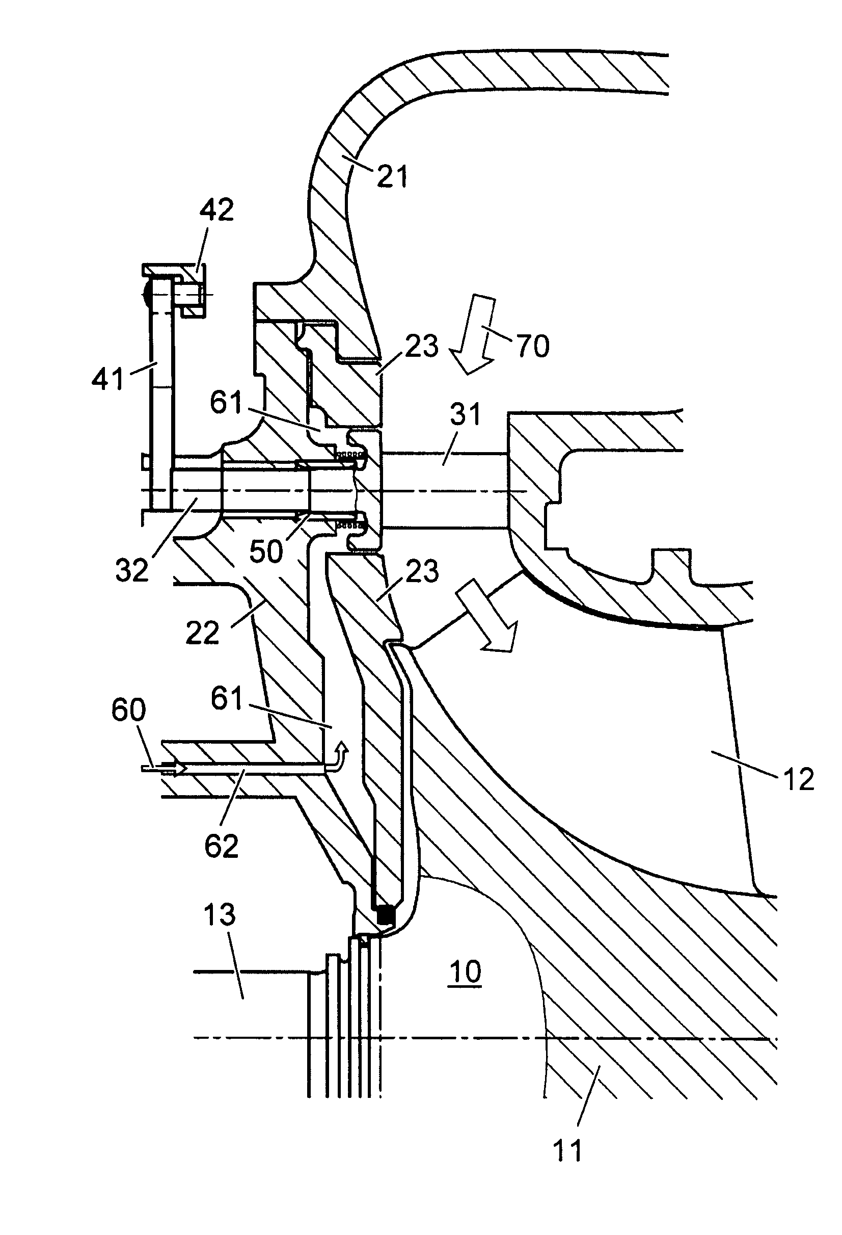
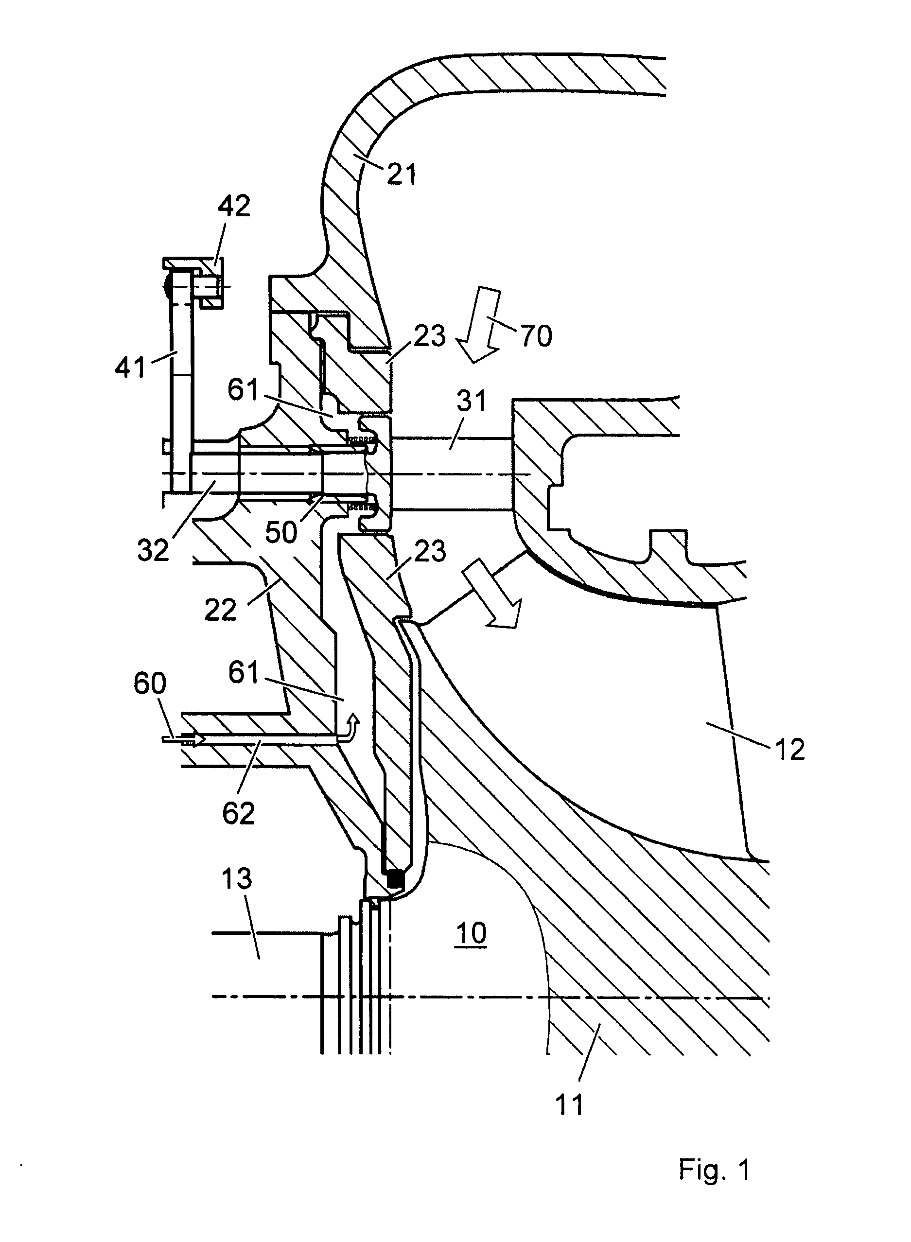
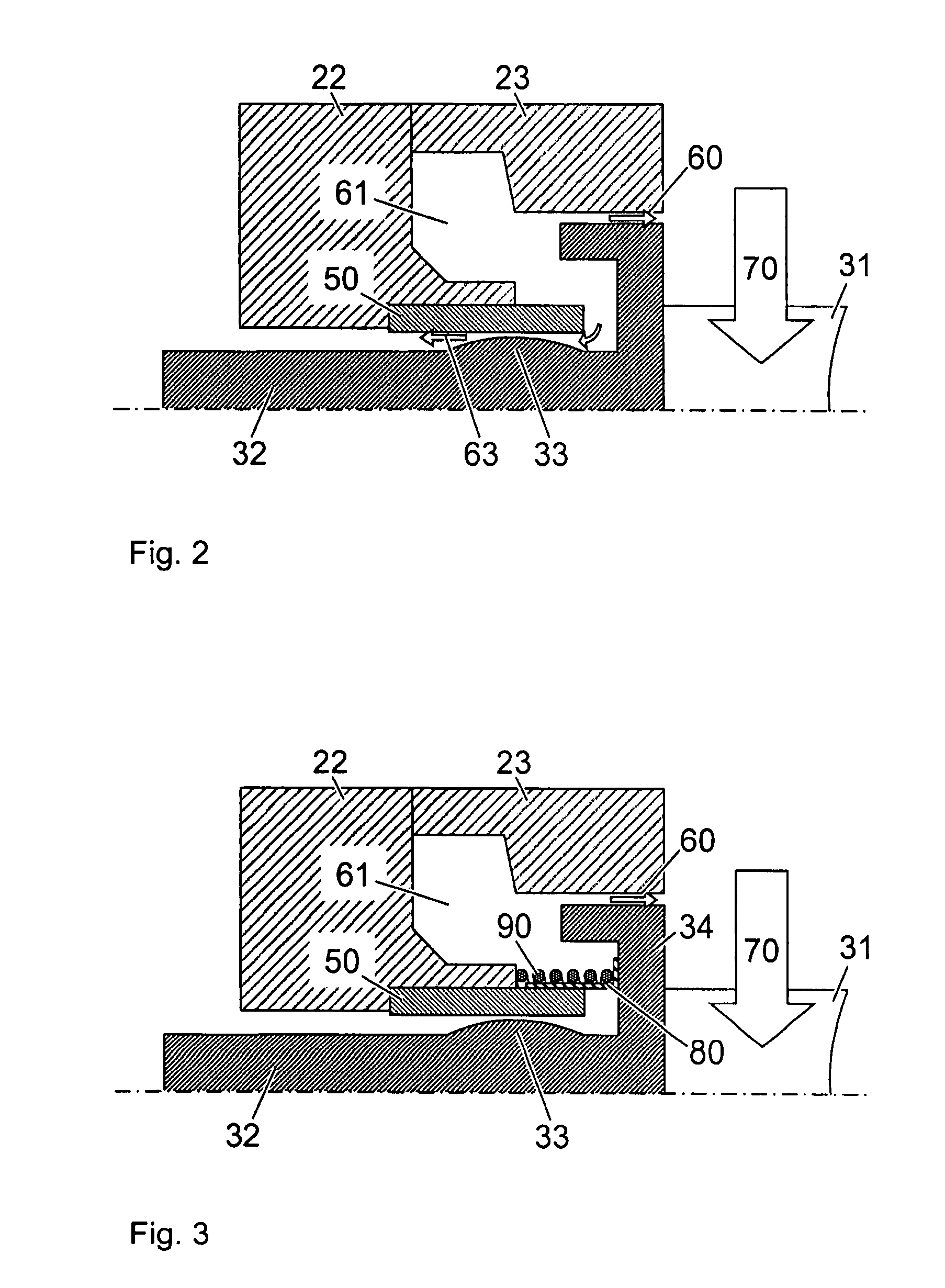
[0015]FIG. 1 shows the turbine side of an exhaust gas turbocharger with a turbine wheel 10 which is arranged in a turbine housing. The turbine wheel comprises a hub 11 and rotor blades 12 which are fastened upon it or manufactured integrally with the hub. The turbine housing comprises a gas inlet housing 21, a bearing housing 22, and also a partition 23 in the back of the hub of the turbine wheel. The partition serves for the thermal shielding of the bearing housing from the hot turbine wheel. It can alternatively also be formed by parts of the bearing housing or the gas inlet housing.

[0016] A guiding device is arranged in the flow passage which leads to the rotor blades. The guiding device comprises variable guide vanes 31 for controlling the exh...


PUM


Abstract

The guiding device of a turbine has guide vanes which are rotatably mounted in the turbine housing. A sealing sleeve is arranged between the turbine housing and the guide vane stem. The additional axial compression spring ensures that the sealing sleeve is continuously pressed onto the guide vane mating contour, and that the axial gap and also the leakage flow are prevented as a result.

Description

RELATED APPLICATIONS [0001] This application claims priority under 35 U.S.C. §119 to EP Application 06405370.5 filed in European Patent Office on 28 Aug. 2006, and as a continuation application under 35 U.S.C. §120 to PCT / EP2007 / 058888 filed as an International Application on 27 Aug. 2007 designating the U.S., the entire contents of which are hereby incorporated by reference in their entireties.TECHNICAL FIELD [0002] The disclosure relates to the field of turbomachines. It refers to the guiding device of a turbomachine, for example of the turbine of an exhaust gas turbocharger, with rotatably mounted, variable guide vanes, and also to an exhaust gas turbocharger with a turbine with such a guiding device. BACKGROUND INFORMATION [0003] Exhaust gas turbines, for example of turbochargers, are used in conjunction with an internal combustion engine. The exhaust gas from the internal combustion engine in this case is used as a propulsive means for driving the turbine wheel. The turbine whe...

Claims


Application Information

Patent Timeline
IPC IPC(8): F01D17/12
CPCF01D11/00F01D11/02F05D2260/30F05D2220/40F05D2240/55F01D17/165F02C6/12F01D17/16F02B37/00
Inventor SCHLIENGER, JOELKOPP, ADRIAN
Owner ABB TURBO SYST
Why Eureka
Try Eureka