
Display module, manufacturing method thereof and electronic device

a display module and manufacturing method technology, applied in the field of display, can solve the problems of low yield rate of flexible oled display in full lamination, failure to repair flexible oled display, damage to flexible oled display, etc., and achieve the effect of improving the successful repair rate of the display module and facilitating the loss of viscosity

Active Publication Date: 2020-12-29
WUHAN CHINA STAR OPTOELECTRONICS SEMICON DISPLAY TECH CO LTD
View PDF10 Cites 2 Cited by
  • Summary
  • Abstract
  • Description
  • Claims
  • Application Information

AI Technical Summary

Benefits of technology

The present patent proposes a display module that uses an ultraviolet (UV) release adhesive layer instead of an adhesive layer between a cover layer and a polarizing layer. This layer is easier to repair and has a higher success rate. The use of UV light to release the adhesive layer's viscosity also makes it easier to separate the adhesive layer from the polarizing layer. Overall, this change in the adhesive layer improves the manufacturing process and quality of flexible OLED displays.

Problems solved by technology

However, due to immaturity of full lamination technology for the flexible OLED display, the yield rate of the flexible OLED display in full lamination is quite low.
Furthermore, the flexible OLED display is characterized by that a slit easily produces in an encapsulating layer whenever the force tears the encapsulating layer, resulting in damage to the flexible OLED display.
As a result, the flexible OLED display fails to be repaired.

Method used


Image

  • Display module, manufacturing method thereof and electronic device
  • Display module, manufacturing method thereof and electronic device

Examples


first embodiment

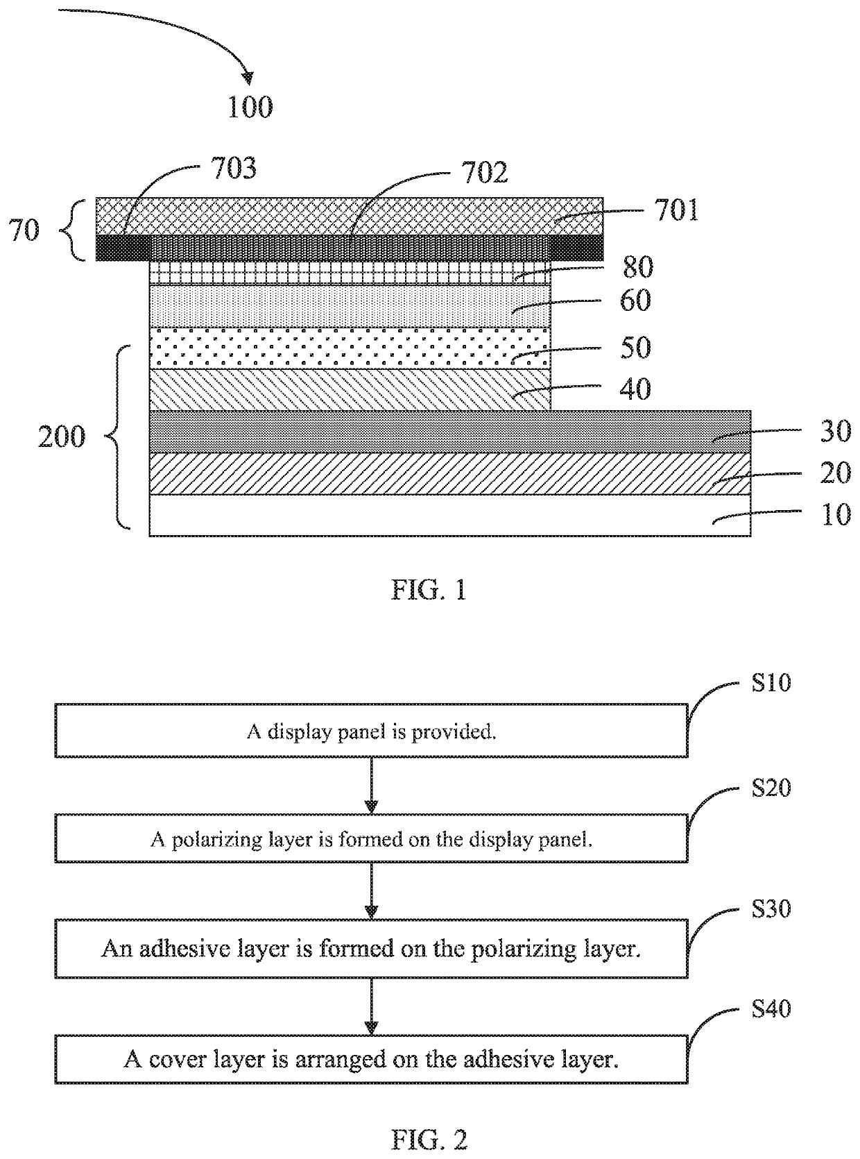
[0033]Please refer to FIG. 1 illustrating a structural diagram of a display module 100 formed by film layers according to the present disclosure.

[0034]The display module includes a supporting layer, a back plate layer 10, and a display panel 200.

[0035]The supporting layer (not illustrated) serves as a substrate of the display module. The supporting layer is mainly configured to support a film layer structure on the supporting layer.

[0036]The back plate layer 10 is arranged on the supporting layer.

[0037]The display panel 200 is arranged on the back plate layer 10.

[0038]In one embodiment, a display panel may be an organic light-emitting diode (OLED) display or may be a flexible display of other kinds, which is not limited in the present disclosure.

[0039]The display panel includes a substrate 20 and a thin film transistor (TFT) layer 30 arranged on the substrate 20.

[0040]In another embodiment, a substrate 20 may be a flexible substrate. The flexible material for the flexible substrate ...

second embodiment

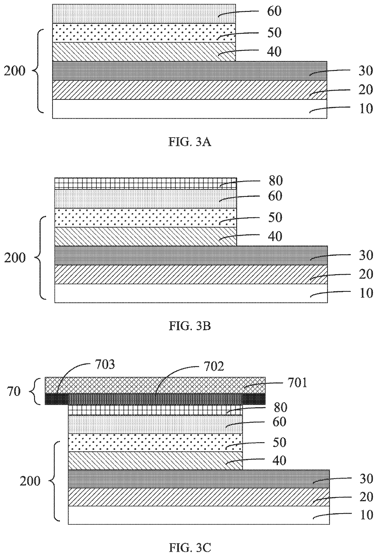
[0065]Please refer to FIG. 2 illustrating a flowchart of a method of manufacturing the display module according to the present disclosure.

[0066]FIG. 3A to FIG. 3C illustrate a flowchart of a method of manufacturing the display module according to an embodiment of the present disclosure.

[0067]The method of manufacturing the display module includes block S10, block S20, block S30, and block S40.

[0068]At block S10, a display panel is provided.

[0069]Please refer to FIG. 3A. The display panel includes a back plate layer 10, a substrate 20 arranged on the back plate layer 10, a thin film transistor (TFT) layer 30 arranged on the substrate 20, a light-emitting device layer 40 arranged on the TFT layer 30, and an encapsulating layer 50 on the light-emitting device layer 40.

[0070]In another embodiment, a display panel may be an organic light-emitting diode (OLED) display or may be a flexible display of other kinds, which is not limited in the present disclosure.

[0071]The display module furth...


PUM

PropertyMeasurementUnit
viscosityaaaaaaaaaa
areaaaaaaaaaaa
flexibleaaaaaaaaaa

Abstract

The present disclosure proposes a display module, a manufacturing method, and an electronic device. The display module includes a display panel, a polarizing layer on the display panel, a cover layer on the polarizing layer, and an adhesive layer between the polarizing layer and the cover layer. The adhesive layer is a viscosity-releasing adhesive layer.

Description

RELATED APPLICATIONS[0001]This application is a National Phase of PCT Patent Application No. PCT / CN2019 / 070290 having International filing date of Jan. 3, 2019, which claims the benefit of priority of Chinese Patent Application No. 201811464859.2 filed on Dec. 3, 2018. The contents of the above applications are all incorporated by reference as if fully set forth herein in their entirety.FIELD AND BACKGROUND OF THE INVENTION[0002]The present disclosure relates to the field of display, and more particularly, to a display module, a method of manufacturing the display module, and an electronic device adopting the display module.[0003]As the development of flexible organic light-emitting diode (OLED) displays, which are widely applied in the display industry, more and more high-end cellphones adopt a flexible OLED display instead of a liquid-crystal display (LCD) display of the related art.[0004]However, due to immaturity of full lamination technology for the flexible OLED display, the y...

Claims


Application Information

Patent Timeline
Patent Type & Authority Patents(United States)
IPC IPC(8): H01L51/52H01L51/56
CPCH01L51/5293H01L51/56H01L51/5246H01L2251/56H01L2251/5338H10K59/8791H10K59/873H10K50/868H10K50/8426H10K71/00H10K2102/311
Inventor TANG, WEI
Owner WUHAN CHINA STAR OPTOELECTRONICS SEMICON DISPLAY TECH CO LTD
Learn More