Bus driver module with controlled circuit and transition controlled circuit thereof

a technology of control circuit and bus driver module, which is applied in the direction of logic circuit coupling/interface arrangement, data switching network, pulse technique, etc., can solve the problems of poor emi performance and no one discloses any technique for smooth transition, and achieves precise control ability of output dc voltage level.

Active Publication Date: 2021-01-12
AMAZING MICROELECTRONICS
View PDF16 Cites 3 Cited by
  • Summary
  • Abstract
  • Description
  • Claims
  • Application Information

AI Technical Summary

Benefits of technology

[0007]In order to overcome the above mentioned disadvantages, one major objective in accordance with the present invention is provided for a novel and creative transition controlled circuit which can successfully solves the problems of prior arts and achieve precise control ability for output DC voltage level as well as multiple phase accelerating transition and smoothing transition for controller area network bus application systems.

Problems solved by technology

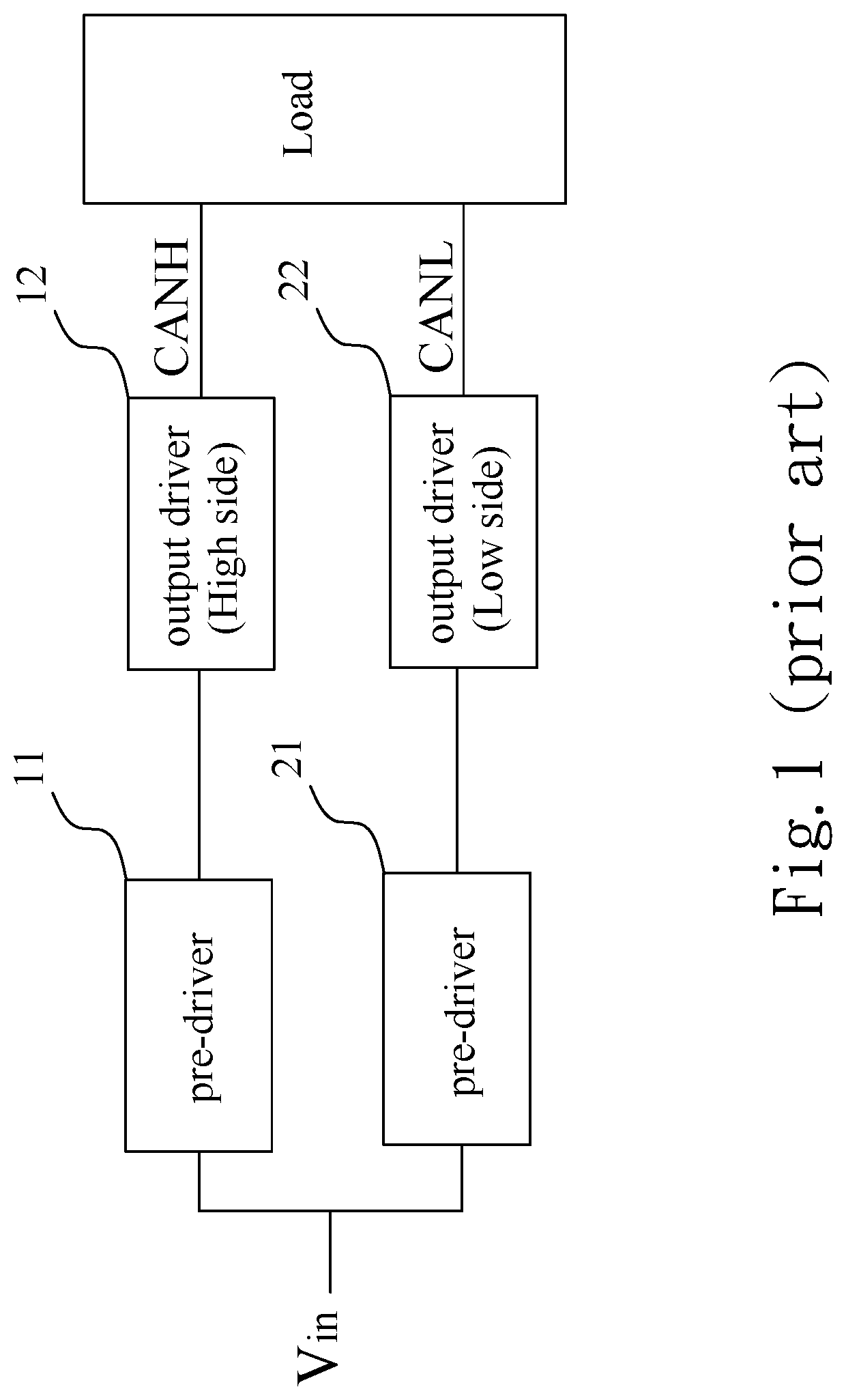
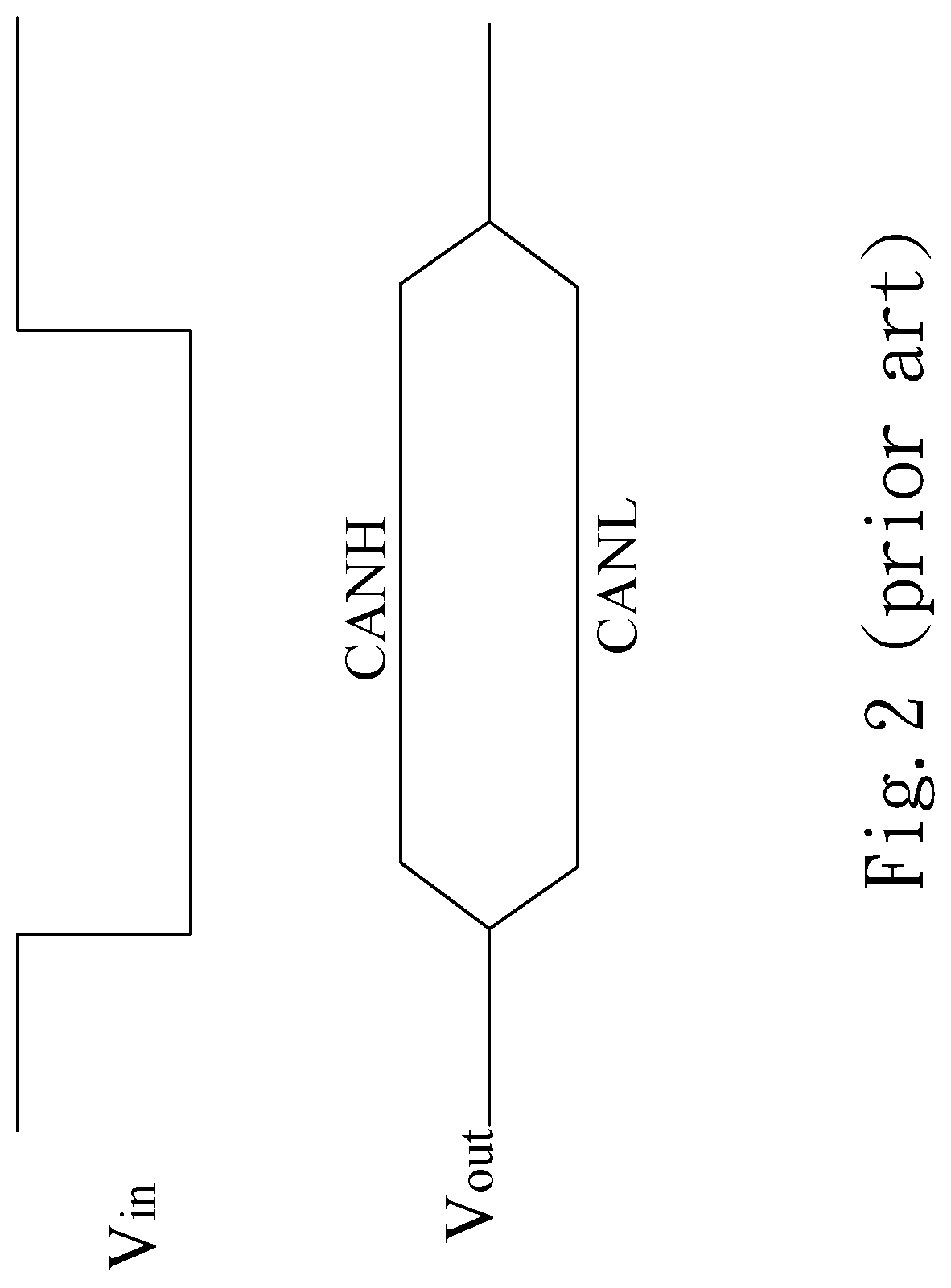
Nevertheless, none of these disclose any techniques for such a smooth transition.
That is to say, when it comes to a bus transition period, a turning point of the transition would be too sharp, leading to a bad EMI performance.

Method used


Image

  • Bus driver module with controlled circuit and transition controlled circuit thereof
  • Bus driver module with controlled circuit and transition controlled circuit thereof
  • Bus driver module with controlled circuit and transition controlled circuit thereof

Examples


Embodiment Construction

[0035]Reference will now be made in detail to the preferred embodiments of the present invention, examples of which are illustrated in the accompanying drawings. Wherever possible, the same reference numbers are used in the drawings and the description to refer to the same or like parts.

[0036]The embodiments described below are illustrated to demonstrate the technical contents and characteristics of the present invention and to enable the persons skilled in the art to understand, make, and use the present invention. However, it shall be noticed that, it is not intended to limit the scope of the present invention. Therefore, any equivalent modification or variation according to the spirit of the present invention is to be also included within the scope of the present invention.

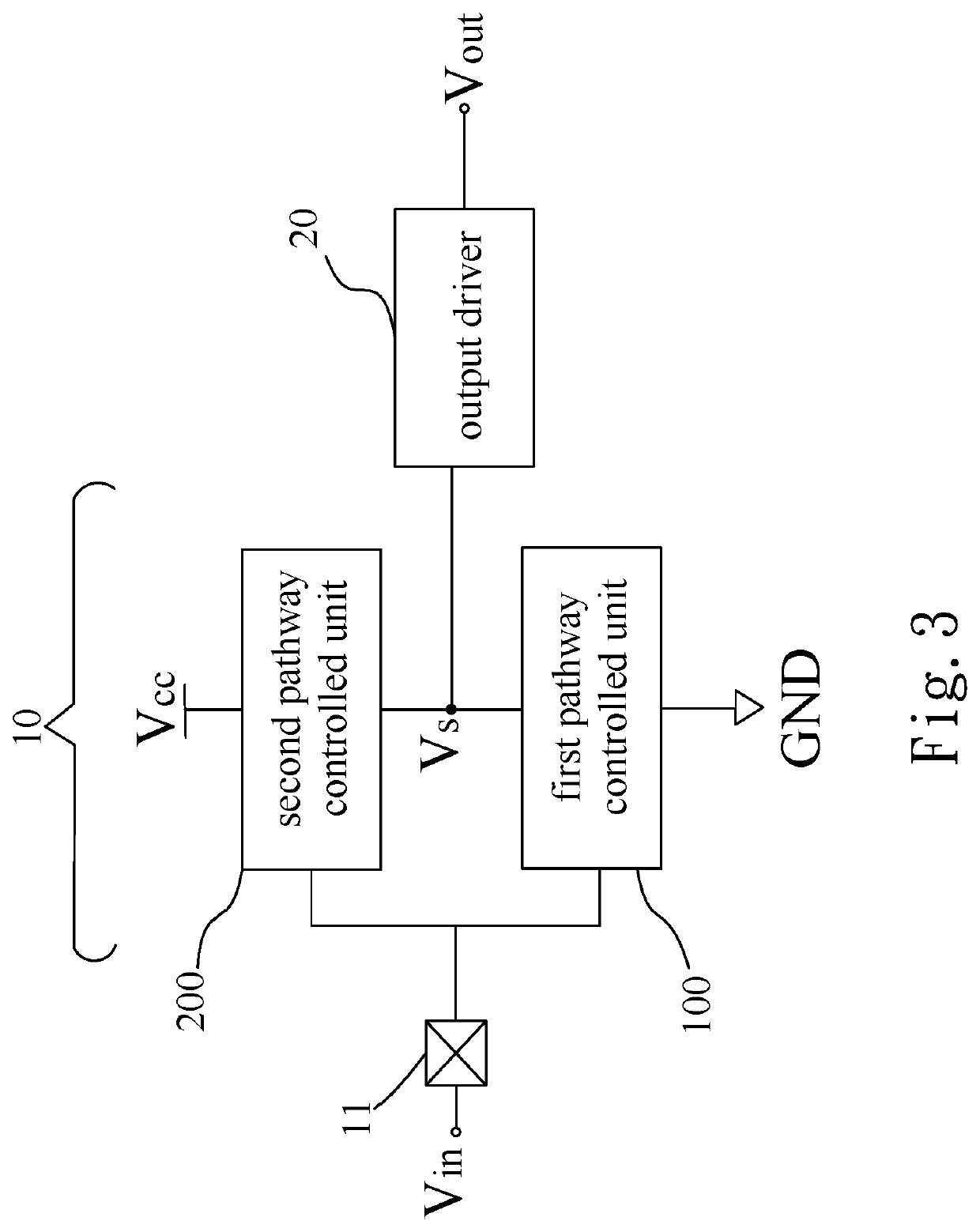
[0037]Please refer to FIG. 3, which shows a block diagram of a bus driver module with controlled circuit in accordance with one embodiment of the present invention. As shown in FIG. 3, the bus driver module wit...


PUM


Abstract

A bus driver module with controlled circuit is connected to a controller area network bus for generating a high side output or a low side output, comprising a transition controlled circuit and an output driver. The transition controlled circuit comprises a first pathway controlled unit connected in parallel with a second pathway controlled unit for generating a side switching voltage. The output driver is connected in series with the transition controlled circuit and receives the side switching voltage so as to accordingly generate the output bus signal. Each of the first and second pathway controlled unit comprises a plurality of switches and can be activated depending on an input signal. By controlling the switches of the first or second pathway controlled unit to be sequentially turned on and off successively, the side switching voltage is characterized by a smooth phase transition, low common mode noise and better EMI performances.

Description

BACKGROUND OF THE INVENTIONField of the Invention[0001]The present invention is related to a control circuit, and more particularly to a transition controlled circuit which is employed with multiple phase accelerating transition and smoothing transition for controller area network bus application systems.Description of the Prior Art[0002]As known, controller area network (CAN) is a kind of specification established in early 1990's, got standardized as ISO 11898-1 in 1993, and widely used in all kinds of vehicles and electronic devices later on. In general, controller area network includes a serial bus, which provides high security level and efficient real time control. Also, it is able to ensure debugging and priority determining mechanism, thereby making transmissions for internet messages much more reliable and efficient than ever. From such a point of view, it is believed that the controller area network nowadays is not only characterized by highly flexible adjustment ability whi...

Claims


Application Information

Patent Timeline
Patent Type & Authority Patents(United States)
IPC IPC(8): H03K19/0185H03K5/13H04L12/40H03K19/20
CPCH03K19/0185H03K5/13H04L12/40013H03K19/20H04L2012/40215H03K17/06H04L12/40
Inventor LEE, CHE-CHENG
Owner AMAZING MICROELECTRONICS
Why Eureka
Try Eureka