
Processing digital image to remove unwanted portion

a digital image and unwanted portion technology, applied in image enhancement, image analysis, instruments, etc., can solve the problems of unsatisfactory inspection results, waste of computing resources, unnecessarily time-consuming, etc., to achieve automatic and accurate detection of regions of interest, and less time per test object

Active Publication Date: 2021-01-19
FUJITSU LTD
View PDF11 Cites 0 Cited by
  • Summary
  • Abstract
  • Description
  • Claims
  • Application Information

AI Technical Summary

Benefits of technology

[0023]A method and apparatus according to the embodiments can enable automatic and accurate detection of regions of interest in an image. By filtering out irrelevant data (for example, noise or extraneous portions) in an image, visual inspection of the image by a technician may be made easier and / or more efficient.
[0024]For example, by automating parts of the inspection process related to ultrasound scan data analysis, quality control engineers / technicians can carry out their inspections in more efficient ways, taking less time per test object and hence reducing the overall human effort and costs. A method / apparatus in accordance with the embodiments is particularly (but not exclusively) useful when applied to NDT ultrasound images where the test object includes a large structure such as a back wall.
[0025]Furthermore, automatic defect detection using a machine learning methodology may be made possible. Training data for machine learning-based defect detection approaches may be generated using a method / apparatus embodying the present invention.

Problems solved by technology

Although the operators are highly-trained, the inspection is not guaranteed to have full coverage of all defects due to noise in the raw data, resulting from the propagation of echoes, and / or issues with the visualisation.
In other technical applications, non-ultrasound images, such as photographs, still video images, etc., may be automatically examined to determine whether particular objects are present in the image, but where only a portion of the image is relevant and / or of interest, this process can be wasteful of computing resources and unnecessarily time-consuming.

Method used


Image

  • Processing digital image to remove unwanted portion
  • Processing digital image to remove unwanted portion
  • Processing digital image to remove unwanted portion

Examples


example

[0069]A particular application of an image processing method embodying the present invention will now be described with reference to FIGS. 12 to 17.

[0070]For example purposes, we consider a fiberglass pipe 120 as the test object. Fiberglass is widely used in manufacturing of large structures that benefit from being light weight, while having high strength and durability properties. Early applications of fiberglass came from the aviation and aerospace industries for aircraft design. Nowadays, there are many other applications including ship hulls, pipes, surfboards, wind turbine blades, automobile body parts, water slides, pole vaulting poles, among others. Any manufacturing anomalies in such objects can have a significant impact on their structural integrity.

[0071]Ultrasonic NDT scanning is performed by an array of probes 121, which emit sound waves that propagate inside the pipe structure 120 and receive the echoes resulting from interactions with its front and back walls (FIG. 12)...


PUM


Abstract

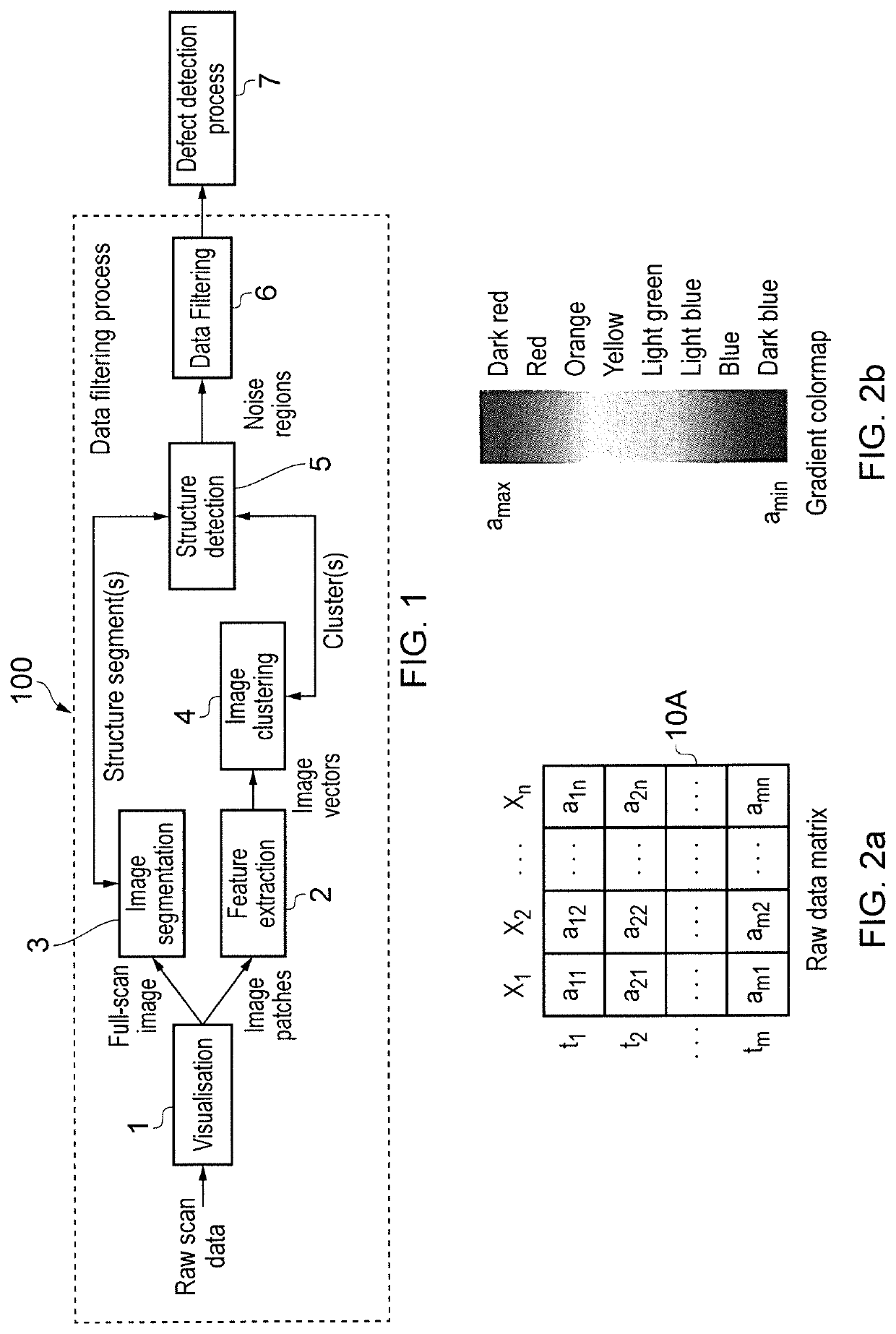
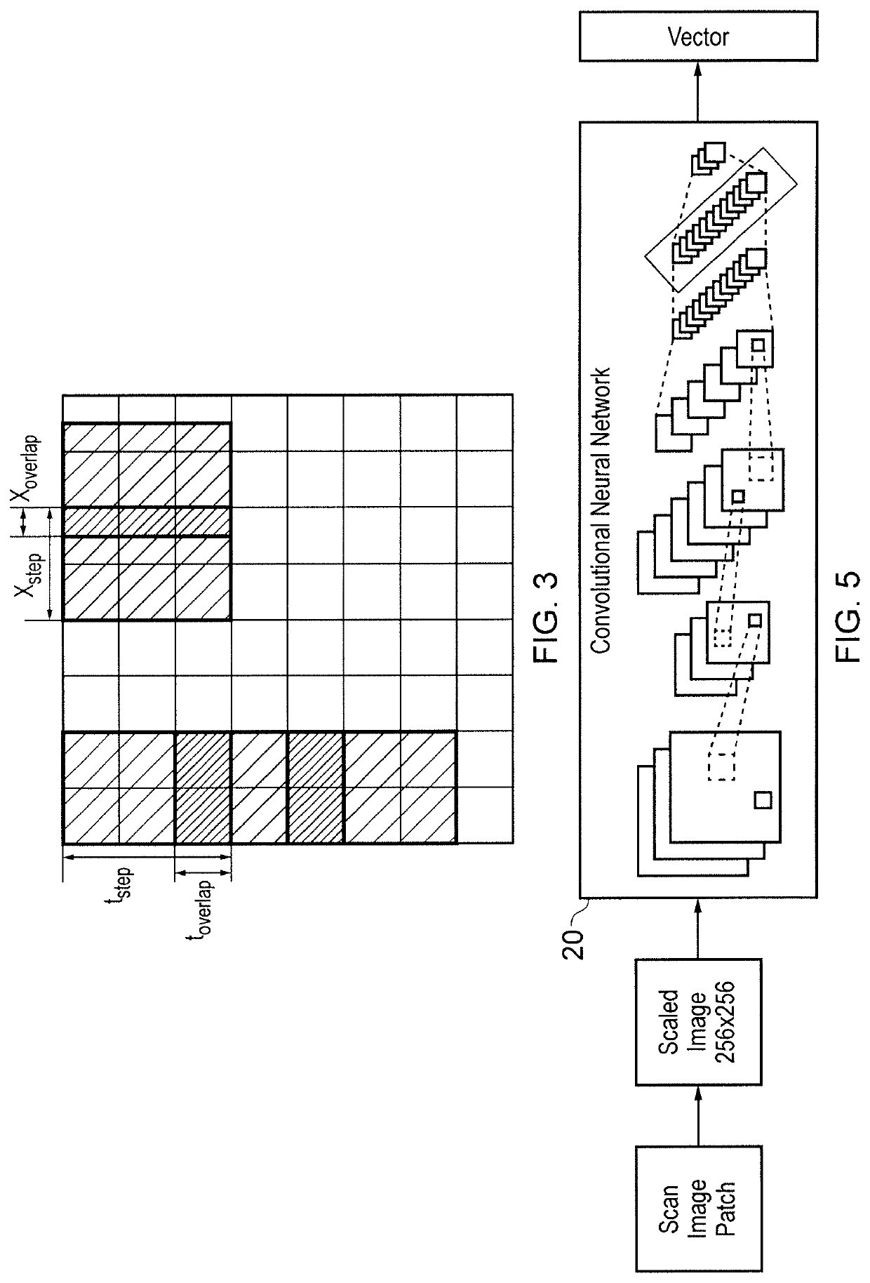
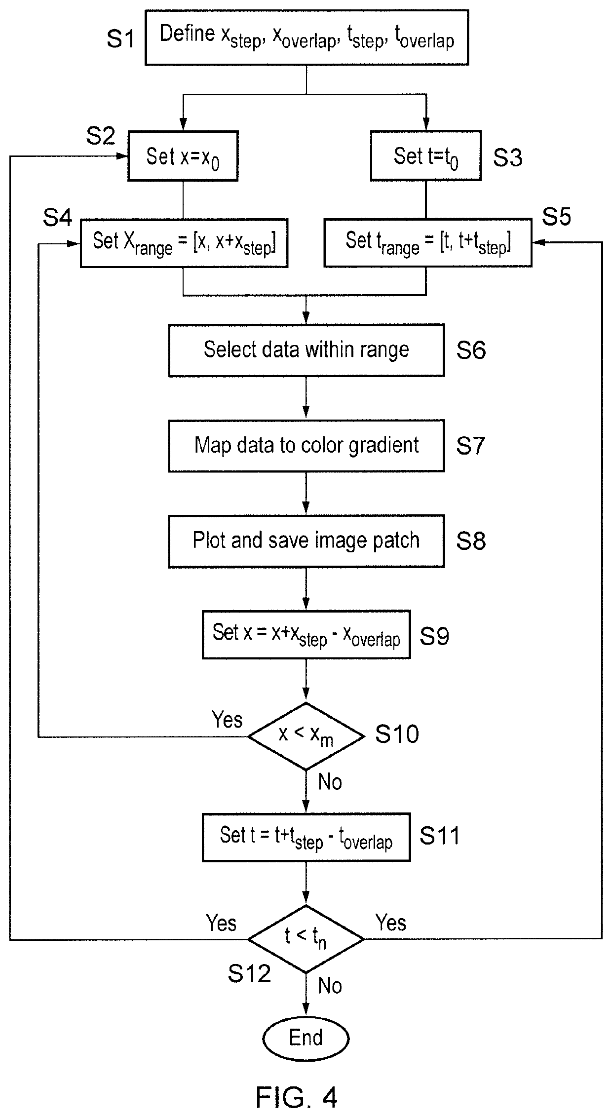
An image processing method to sample the image to generate patches. Feature vectors are extracted from the patches, and the extracted feature vectors are partitioned into clusters, where feature vectors in the same cluster share a common characteristic. A portion of interest in the image is segmented. An aggregate bounding region creation process is carried out by finding the largest segment and creating a bounding box around it; determining which cluster contains the most patches within the bounding box of the segment; and adding the patches of the determined cluster to an aggregate bounding region for the portion of interest. The aggregate bounding region creation process is repeated for each other segment in order of size. The resulting aggregate bounding region contains all the patches associated with the portion of interest. The patches which fall outside the resulting aggregate bounding region are then removed from the image.

Description

CROSS-REFERENCE TO RELATED APPLICATIONS[0001]This application is a continuation of International Patent Application No. PCT / GB2017 / 053050, filed on Oct. 9, 2017 which is based on and claims the benefit of U.K. Application No. 1617444.3, filed Oct. 14, 2016, in the United Kingdom Intellectual Property Office, the disclosures of which are incorporated herein by reference.BACKGROUNDField[0002]Embodiments discussed herein relate to an image processing method for removing an unwanted portion of a digital image, and a corresponding image processing apparatus and computer program.Description of the Related Art[0003]An image, such as an image of a location or an object, may contain information which allows certain tasks to be performed. For example, an image such as an ultrasound scan of an object can be analysed to identify structural defects within the object, as discussed in more detail below, or a photograph or still video image can be examined to determine whether a particular item is ...

Claims


Application Information

Patent Timeline
Patent Type & Authority Patents(United States)
IPC IPC(8): G06T7/11G06T7/187G06T7/00
CPCG06T7/11G06T7/0004G06T7/187G06T2207/10132G06T2207/20021
Inventor MENDES RODRIGUES, EDUARDAGEORGESCU, SERBANTOWNSEND, JOSEPH
Owner FUJITSU LTD
Learn More