High voltage high efficiency valve

a high-efficiency, valve technology, applied in the direction of valve housing, valve operating means/release devices, dc motor rotation control, etc., can solve the problems of difficulty in being useful and the diminution of the need to cool the coil, and achieve the effect of high efficiency and effective control of conditions

Active Publication Date: 2021-01-26
TACO
View PDF21 Cites 0 Cited by
  • Summary
  • Abstract
  • Description
  • Claims
  • Application Information

AI Technical Summary

Benefits of technology

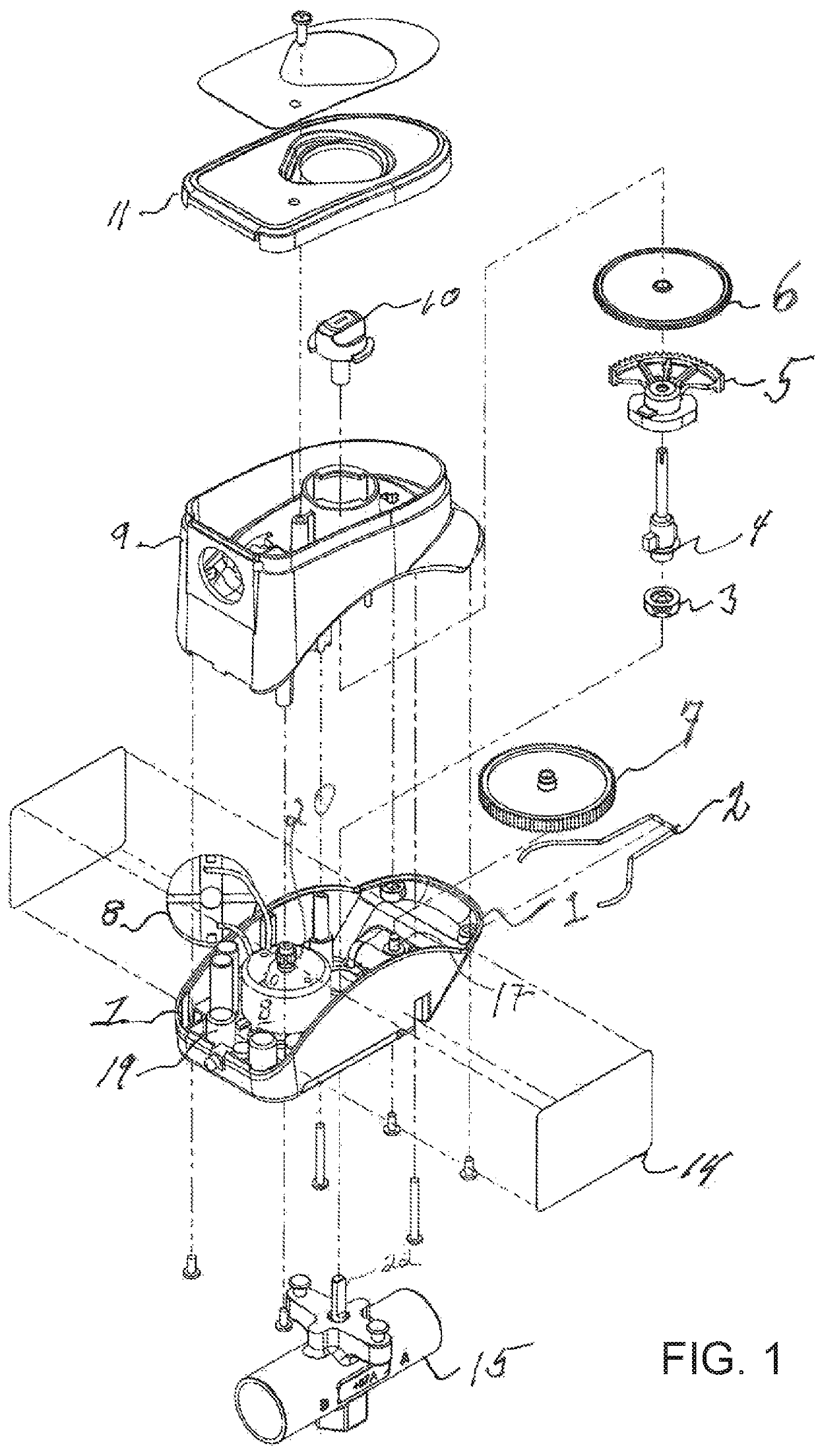
[0005]A high voltage zone valve motor and its control system according to the present invention provide a highly efficient and effective control over the conditions in an enclosed environment, such as a commercial or residential building having multiple zones requiring different conditions determined by the flow of fluid to each of the zones.

Problems solved by technology

A typical present day SMES system includes a superconducting coil, power conditioning system and refrigerator, which makes it very difficult to be useful in the present system; as new materials are developed the need to cool the coil may be diminished to the point that a refrigerant system may no longer be necessary.

Method used


Image

  • High voltage high efficiency valve
  • High voltage high efficiency valve
  • High voltage high efficiency valve

Examples


Embodiment Construction

[0022]Hereinafter, embodiments of the invention will be described in detail with reference to the accompanying drawings, and the details necessary for those skilled in the art to understand the contents of the invention will be described in detail. However, the invention may be embodied in many different forms within the scope of the appended claims, so the embodiments described below are provided merely as examples.

[0023]Unless otherwise defined, all terms (including technical and scientific terms) used herein have the same meaning as commonly understood by one of ordinary skill in the art to which this invention belongs. It will be further understood that terms, such as those defined in commonly used dictionaries, should be interpreted as having a meaning that is consistent with their meaning in the context of the relevant art and the invention, and will not be interpreted in an idealized or overly formal sense unless expressly so defined herein.

[0024]Embodiments are described her...


PUM


Abstract

A zone valve control system for a flow valve comprising a direct current rotary electric motor connected to a valve shaft, an electronic control system comprising a microprocessor, an electric measuring device for signaling the presence of a predetermined electrical stall current, a rectifier and a regulator to convert and regulate external AC voltage to a desired DC power output; and an electrical storage system having a total storage capacity sufficient to power the DC electric motor to move the valve between the closed and opened positions; an external sensor for signaling when a certain condition exists in an external zone; the microprocessor controlling the flow and polarity of DC current to the motor; whereby the electronic control system controls movement of a valve operably connected to the output shaft to open or close a valve to maintain a desired predetermined condition in the external zone.

Description

[0001]The present invention relates to a high voltage zone valve.BACKGROUND OF THE INVENTION[0002]Current high voltage zone valves use a synchronous motor and a return spring. In the synchronous motor design, the motor is used to open the valve and a tensed return spring is used to close the valve. The use of a constantly tensed return spring to close the valve, requires that to maintain the valve in the open position a voltage must be constantly applied to the motor the entire time the valve is open. Constantly maintaining a stall current on and running through the motor while the valve is open, makes this energy inefficient. The other disadvantage of this design is that synchronous motors require a specific voltage, so that they cannot be used interchangeably when a different voltage is available.[0003]Other types of zone valves include the use of a small shaded-pole synchronous motor combined with a rotary switch that can disconnect the motor at either of the two stopping points ...

Claims


Application Information

Patent Timeline
Patent Type & Authority Patents(United States)
IPC IPC(8): F16K27/02H02P7/03G05D23/19F16K43/00
CPCF16K27/029F16K27/0236F16K43/001G05D23/19H02P7/04F16K19/003F16K31/046F16K31/055
Inventor KELLICKER, ROBERTBRINDAMOUR, JR., RICHARD F.CARREIRO, ROBERT J.
Owner TACO
Why Eureka
Try Eureka